My measurements for the DIY Sony VFET N-Channel are very similar to yours, Peppe.
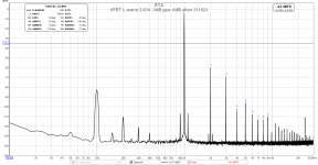
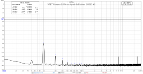
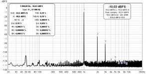
See below my REW measurements for 1W and 5W into 8 Ohms.
Nelson mentioned in his article that the N-Channel version is more susceptible to PSU ripple / noise than the first version (P-Channel), and that's why he put in the additional RC cell on the power supply filter. Well, we can see the effect of the higher susceptibility to PSU noise in our measurements 😀.
However, on my 100 dB/W sensitive speakers, I still only hear a faint hum from the amp,audible only within less than 30 cm of the speaker driver.
I will actually follow ClaudeG's example of adding a PO89ZB to each channel to see if this will do something not only to the HF noise, but to the 100 Hz ripple as well ... after all, each filter has about 900uF of capacity in it as well. Just waiting on my new run of filter PCBs with mounting holes to be delivered.
Best regards, Claas
Attachments

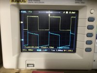
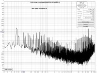
I'm also eager to try some of the new front end cards Mark Johnson has developed. As you can see below, the frequency response of the Sony DIY VFET has some "peculiarities" 😀
It's actually the Edcor, as my M2 has a similar overshoot / ultrasonic resonance, and my SissySIT (which uses Cinemag transformers) has none of it - totally clean square waves.
That's why I want to try a few different front ends - at least one without a transformer, and one with a different transformer than the Edcor. I'm not certain yet if I would spring for another pair of Cinemags ... they are a bit expensive over here. Then I probably would do a veroboard adapter to fit different transformers into the Edcor footprint.
Also waiting on the PCBs for the different frontends to be delivered ...
I'm really interested to hear what sonic differences frontends will bring that would measure very differently ...
Best regards, Claas
Attachments

Mains frequency in your country is 50Hz?
Correct.
And room lights (ikea dimmable led bulbs) off has no effect but good point. I had unplugged the desk lamp but left the room light on...
Thanks chede for the feedback. You confirmed it is not my measurements the problem. Nor it is the 100 Hz ripple (I can't hear it on my 90 dB speakers). 😎
Looking forward to seeing what you achieve with the PO89ZB. 🙂
Hallo Class,
Interesting, let us know how it sounds!
Just as a side note for all, I tried (and fitted permanently) the SMPS filters on a P-Channel VFET, which is a bit different than the N-VFET (less filtering to start with, but also more PS rejection per se). So it shall be interesting to read how the filters addition fare with N-VFET, you will be the first one to find out!
If my theory is correct, I see some hope as your original filter, as mine, has a low Fc but no coil for the XXX kHz garbage...
Also interesting to see what you can measure... and hear. Normaly, eventhough I have 1500uF after each filter at OS board's entry, sadly Fc shouldn't still be in a frequency range where you filter out 100Hz (the original filter is better suited for that), but let's measure and... who knows?
Grüsse an Dü
Claude
Some thinking on the N-VFET... A UNIT I DON'T OWN and I that's just "quickly" thinking out loud!
Looking quickly at the N-VFET schematic, and I mean quickly... hence I could be wrong...
My understanding is the filter provided by Papa is a first order filter with Fc roughly 50Hz, and that RC network has been doubled to provide, I guess (?), some channel separation as each RC seems to feed an OS board. Note that would be very different from my N-VFET.
The simplified theory says that filtering should be 9dB at 100Hz (-3dB and 6dB/octave filter) but we all know that it is too simplified as filters "need to get started" to get their slope coefficient. Make that a bit less, so not great.
What can be done to improve on the 100Hz filtering given the existing hardware?
One simple solution would be to connect the OS PS in such a way that both RC network feed a single PS line, forming effectively a RCRC filter network. Basicaly that would double the filtering while baring no real electrical risk as all is dimensioned for it. There are some negatives though:
- you double the voltage losses at the filter (2Rs), effectively losing up to 1.9V vs the original set up. Not sure this is an operational issue (?) unless seeking for absolute max power (which you shouldn't anyway wuth this unit IMHO), the bias may though need to be adjusted again
- you obviously lose the channel separation that was probably intended first hand (and wise Papa probably did it for a reason), meaning channel crosstalk could become a problem... but adding extra SMPS filters as I did may help on that regard
- you still don't get a great 100Hz filtering, but well, better than before obviously and the test is quickly performed to see the trend!
Another way would be to add capacity, or Rs in the RC network. There might be a problem there. That is starting with a lot of capacities without triggering the hiccup mode of the SMPS, so a softstart is IMHO required if you really want some worthwhile additional capacity. That is easily done, small board and cheap.
Say you more than double the Cs, fitting 2200uF instead of the existing 1000uF caps, provided yours fit... you half Fc down to 21Hz and you kind of double your filtering without altering anything (channel separation, schematic). Now if you are willing to double your voltage losses, you double your filtering again. It gets interesting.
You can achieve that easily either by:
- connecting as in the very first paragraph to get RCRC, but then you lose the separate channel filtering (at this stage at least, additional SMPS filters could help recovering some)
- keeping separate RCs filters per channel, but fitting R=2 resistors, well noting then these need to be able to cope with the extra heat (more W, or more in parallel)
That's it for this morning. Just thinking out loud how one could easily experiment regarding some additonal 100Hz filtering... should that really be a problem for (some) N-VFET owners ! Again, please check your measurements, check the effect of the small additional SMPS filters as Claas will implement them... and also trust your ears for any improvement or issue... as we don't hear with scopes 🙂
I hope it helps
Claude
Some very last thinking, BUT I am not familiar with SMPS internals so that would require more knowledge here as one needs to understand where the 100Hz come from...
One option could be fitting an external 100Hz filter at main's level, that is upstream of the SMPS, probably not easily done re harware not to mention high voltage risks for DIYer. And if some 100Hz is not just passed through but also produced at SMPS level, then this is bad. Requires no softstart though and some of you may have some huge 100Hz filters avail?
Another option would be fitting an external 100Hz filter at the SMPS output, but still upstream of the VFET, so offboard to have more space. Probably still not easily done either if you want to reduce voltage losses (hence big caps and big board) but apart from the special connectors at least that one looks like a safer bet re filtering, playing with large caps (or inductors) to keep Rs (or Ls) low... and is still easier to do than a linear regulated supply. Requires a softstart though.
Again, one has to ponder first... is there really any problem... or rather a way to (reasonably) improve sonicaly on the existing??? Again, we don't listen with a scope... and both solutions are way more costly and take space to, if you do the maths with reasonable values, lead in most cases to marginal improvements at 100Hz vs my first suggestions (which are IMHO easier to perform)
Claude
Last edited:
Something else to try...
Any one (or two) of the newer front end cards by Mark J. All have more extensive filtering of the power supply voltage. Two of them (Dreadnought & Marauder) go as far as regenerating a local supply using an on-board DC-DC converter to boost the supply voltage to 58V. These boards eliminate the Edcor transformer in favor of a higher gain circuit. The other two boards (Bulwark & Scourge) keep the Edcor as part of their gain structure, with the Bulwark allowing for more gain by adjusting a feedback resistor network. The Scourge is the simplest of the four to build, and I have been happy with the sound of mine as they are running in.
Any of these designs will noticeably improve stereo separation, and reduce any 100 Hz noise that is leaking from the kit SMPS brick. They each have variations in sonic character (small yet noticeable) and are fun to listen to.
It is also worth noting that all FE cards that use the Edcor have a Zobel network on the output which can be tweaked a little to improve the square wave response. I have used 330 pF polypropylene caps in place of the 220 pF ceramic with good results, and can recommend this mod to those willing to try it and see how it looks on the scope.
Have a careful look at the N-channel VFET (second batch of amplifiers) pdf written by Nelson Pass, particularly the bottom paragraph on page 1.
Chede, I was wondering if you are AC coupling your probes? I saw those slopes on the lower frequencies as well on the ACA while showcasing my new scope to my dad (who was an electronics engineer all his life).I'm also eager to try some of the new front end cards Mark Johnson has developed. As you can see below, the frequency response of the Sony DIY VFET has some "peculiarities" 😀…
Upon seeing those slopes he said: “it looks like you have a capacitor in the signal!”, I mentioned that this is what the AC coupling does and he mentioned that, even though we are measuring AC here, you don’t need it AC coupled to remove any DC, and it introduces those weird slopes on lower frequencies.
Maybe you are experiencing the same thing? It certainly removed those slopes once I DC coupled the scope probe.
If not, it may very well be the response at low frequencies, I haven’t yet connected my VFET to the scope.
Best,
Rafa.
Last edited:
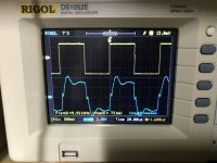
Hi Rafa, good point ! However, the channel on my scope is DC coupled.
I think what we're seeing here is just the bandwidth limiting of the whole VFET path (beginning to end). I get a lower -3 dB point of approx. 4.5 Hz, with a phase shift of 180 degrees.
In comparison, on my SissySIT with Cinemag transformers and only one coupling capacitor in the whole path, I get a lower -3dB point of approx. 2.7 Hz, with almost no phase shift.
Will try to separate out the contribution of the Front End resp. the Edcor to this, but have to wait on the PCBs I ordered, get parts, and build one of the alternative front-ends without transformer.
Regards, Claas
Last edited:
Did you try to do the same measurement with grounded RCA input. Just to check if 100 Hz noise comes via signal or via PSU?
The signal from test generator is probably very clean but "things" can happen via the signal path from generator to amp.
The signal from test generator is probably very clean but "things" can happen via the signal path from generator to amp.
OK, so still -90 dB.
It is quite disappointing for a SMPS.
I am happy I upgraded to a better SMPS for my P-channel version.
I have not yet made any measurements but it is very quiet. No hum with ear to speaker units.
Regarding hum my memory is that the kit SMPS brick was also very quiet......so.....difficult to conclude anything......
Attachments
P channel here (so may be different)... standard brick SMPS that came with the kit... test performed before we tweaked the PS... on Klipsch LS that have advertised efficiency of 98dB/m/W (we all know it is a couple less due to the way Klipsch "measures" it) but still high efficiency
NO HUM OR NOISE WHATSOVER
and that is trying hard, ear directly on horn and volume way up (say 20dB over loud position with music), something I would never do in real life, neither the ear positioning nor the volume LOL
We thought Class D would be quiet... and it is usualy, especialy given all the tweaks we did on Gilles amp, it is nearly dead quiet... but well, my VFET is quieter!
If you hear a hum then IMHO there is defo something wrong womewhere. If it is measurement only and you hear nothing, then (I would say) one can't conclude atthat stage.
Claude
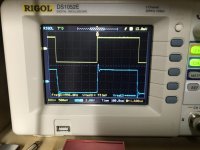
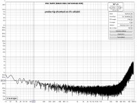
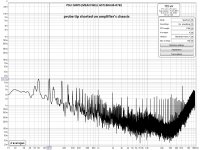
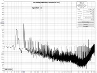
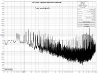
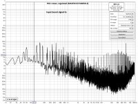
The 100Hz component at speaker-out is 0.34mVrms. I don’t think anyone can hear this.
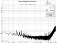
It comes through conduction from the SMPS. There is no radiation inside the amplifier enclosure. (I shielded the input module placing it inside a steel enclosure with no effect).
I did some measurements (inputs shorted) along the DC lines and along the signal lines. The offender comes through conduction from the SMPS. There is no radiation inside the amplifier enclosure. (I shielded the input module placing it inside a steel enclosure with no effect).
George
Attachments
-
 7 probe tip shorted on it's gnd (V).jpg292.6 KB · Views: 86
 -
 6 probe tip shorted on amplifiers chassis(V).jpg313.7 KB · Views: 100
 -
 5 Speaker out (V).jpg316.1 KB · Views: 98
 -
 4 Power board signal in (V).jpg317.7 KB · Views: 86
 -
 3 Input board signal in (V).jpg312.8 KB · Views: 289
 -
 2 PSU filter board DCout (V).jpg313.6 KB · Views: 320
 -
 1 PSU filter board DCin (V).jpg298.5 KB · Views: 336
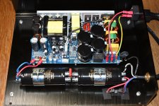
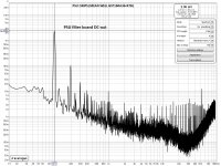
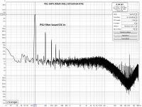
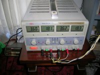
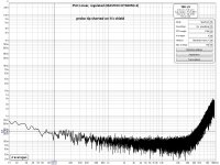
I measured at the same points, this time using a linear regulated PSU.
What is shown is with negative terminal grounded (when floating, there is a stronger 50Hz component)
I prefer the SMPS 🙂
George
What is shown is with negative terminal grounded (when floating, there is a stronger 50Hz component)
I prefer the SMPS 🙂
George
Attachments
-
 DSCN6268.JPG615.9 KB · Views: 144
 -
 7 probe tip shorted on its gnd (V).jpg294.9 KB · Views: 99
 -
 6 probe tip shorted on amplifiers chassis(V).jpg301.4 KB · Views: 100
 -
 5 Speaker out (V).jpg317.4 KB · Views: 111
 -
 4 Power board signal in (V).jpg320 KB · Views: 104
 -
 3 Input board signal in (V).jpg320.6 KB · Views: 100
 -
 2 PSU filter board DCout (V).jpg318.6 KB · Views: 130
 -
 1 PSU filter board DCin (V).jpg320.5 KB · Views: 128


- Home
- Amplifiers
- Pass Labs
- DIY Sony VFET pt 2 (N-Channel Build)