The SMPS is the external "brick".
I have not read all of it......but how does it look with shorted RCA input?
The RCA interconnects could pick some 100 Hz up or it could come from the source?
My guess is that is not the SMPS "brick" at its output.
I do not think it is my sound card since it is the only amp I am seeing it. I will investigating more by shorting the input next week and post some plots.
I do not think it is my sound card since it is the only amp I am seeing it. I will investigating more by shorting the input next week and post some plots.
I had something similar but quite audible. It turned out to be coming from an old fluorescent desk lamp plugged in to the same outlet.
Like all things, there are good ones and bad ones. The best I have used are made by Sami of Micro-Audio. The noise floor is flat as a board from 20Hz to 20kHz down at -130dB. Not even a blip at 60Hz/120Hz/180Hz. The bump I have is from EMI pickup through the air when the SMPS is not even on.
I second the supplies from Sami are very good.
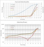
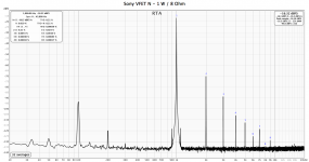
Today I was testing (still on 8Ohm dummy load) the distortion of the amplifier when overdriven.
Not bad. 🙂
George
Can a novice here try to interpret these results? Please no one take my statements as correct until someone verifies them. I'm trying to learn.
First graph says that for a 2.8 Vrms input (a standard value of 2.83?), distortion is approx 1%. This gives 12 Poit (Wavg). Input is a sine wave?
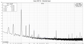
The 2nd graph says the total distortion is dominated by H3, the 3rd harmonic. The 2nd harmonic H2, is several times lower than the total, so doesn't significantly contribute - see the dip at 9 that doesn't impact the total.
Thanks for the info on the wire and such everyone. I really liked working with this wire.
Follow up question. For the power supply O+ shunt to ground I have somehow run out of wire. Because it's a low powered amp, and it only is used on start up, do you see any issue with me using the twisted strand wire for the shunt/relay circuit (From the speaker + output to the O+ on power supply). My sense is this is ok but I haven't built something in years and I'd rather be safe than sorry.
Follow up question. For the power supply O+ shunt to ground I have somehow run out of wire. Because it's a low powered amp, and it only is used on start up, do you see any issue with me using the twisted strand wire for the shunt/relay circuit (From the speaker + output to the O+ on power supply). My sense is this is ok but I haven't built something in years and I'd rather be safe than sorry.
Hi JZatopa,
yes, thin wire to the output shorting relay is no problem. Have done so myself, works perfectly.
Regards, Claas
yes, thin wire to the output shorting relay is no problem. Have done so myself, works perfectly.
Regards, Claas
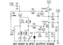
ok, good news. I have an amp playing music. Bad news, after I set p1 to 14V between ground and the IRF 250 case on both channels, and let the amp sit, the left channel dropped to ~7.6V and seems to wander (was fine for about an hour then when I returned after an hour break it was doing this). It's odd because when I adjust the pot the voltage goes up and then drops back to that range and it was working fine when I first powered up the amp. Any ideas on this one? It seems to work but that definitely isn't right. The audio still works and that channel doesn't feel much hotter than the other.
Voltage at V+
Left board 33.9
Right board 33.88
Voltage at case of IRF250
Left board 7.32 (returns to roughly that when I adjust pot)
Right board 14 (holds steady)
V Drop Across R1 and R2
Left board R1 1.313 R2 1.313
Right board R1 1.335 R2 1.335
The screen printing on the 2sk82 on the left channel looks slightly different than the other (the printing is thinner) but I'm not sure that matters.
Last edited:
I am taking some measurements and this is what I'm seeing so far.
Left measurements that seem off vs. right
Measurement - Right - Left
Voltage Drop
R4 - 0 - 0
R7 - 17.61 - 24.07
R8 - .04 - .22
So it looks like something is definitely going on here but nothing looks hot or has smoked. Not sure why it would have been working fine at first and then stopped unless something only slightly blew.
replace P1
Thanks ZM, I ended up re-soldiering last night and the problem seems to have gone away. Running it now to see if it stays that way or needs to be replaced. Thanks for the help.
 to Nelson v2 sound really sweet
Scourge, Bulwark, Marauder, and Dreadnought are now available as full kits including PCB and all electronic components. Yes even the Edcor transformers.
VFET Front End cards :: diyAudio Store
VFET Front End cards :: diyAudio Store
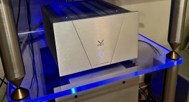
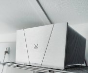
Wow, this little gem totally lives up to the high expectations that I had. Hard to explain, really..
The amp is very quiet driving my horns and CD's. Compared to my F6 and ACA builds I would expect the VFet amp to at least exhibit some hum as well. When I put my head in the horn I hardly hear anything! Maybe it is me taking lots of time and patience building it, but realistically it is probably to the design(ers) merit😉
Happiest audiophile indeed!
For now it is perfect as is, however the just posted FE's are very tempting!
Attachments
Last edited:
Finally I made some measurements.
I have:
- Documented my measurement rig (here)
- Moved signal wires away from heatsink surface
- Made sure that signal cables do not pass anywhere close to the PSU
- Plugged PSU in the other room in an outlet not shared with anything else
- Looked at FFT at 1 W / 8 Ohm and with shorted inputs
I still see the 100 Hz peak and both channels shows identical figures. I haven't tried the amp with high efficiency speakers, so I cannot tell if it will bother me or not.
I am wondering if anyone has seen something similar.
Attachments
Finally I made some measurements.
I still see the 100 Hz peak and both channels shows identical figures. I haven't tried the amp with high efficiency speakers, so I cannot tell if it will bother me or not.
I am wondering if anyone has seen something similar.
Mains frequency in your country is 50Hz?
This is going to sound silly, but did you do the measurements with the chassis fully assembled? And the room lights off?
Why? I recall years ago in an EE lab experiment at university, the room lights were changing the behavior of some diodes. The actual light was the culprit, covering the diodes (paper or electrical tape,, can't remember) changed the response to something closer to expected.
- Home
- Amplifiers
- Pass Labs
- DIY Sony VFET pt 2 (N-Channel Build)