I had the T mounted to the sink... I kept looking at it and shaking my head, so....

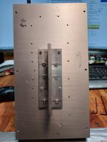
I still have to flatten the sink and T, I'm thinking about taking them to my buddies machine shop 5mins instead of lapping, Iget cramps in my hands these days. The holes aren't perfect, but no bad for eyeball. 😛 They should do the job of cranking that T to the sink. I haven't tapped them yet. I put a peice of tape on a small Allen, so I didn't go to deep. I didn't want to punch through it. I have done so on some higher wattage stuff to make sure, but this should be just fine. I also mounted them in the middle of the sink.
I still have to flatten the sink and T, I'm thinking about taking them to my buddies machine shop 5mins instead of lapping, Iget cramps in my hands these days. The holes aren't perfect, but no bad for eyeball. 😛 They should do the job of cranking that T to the sink. I haven't tapped them yet. I put a peice of tape on a small Allen, so I didn't go to deep. I didn't want to punch through it. I have done so on some higher wattage stuff to make sure, but this should be just fine. I also mounted them in the middle of the sink.

First one done. All holes line up, which is good as I drilled these by hand. Tapping went well, I only had through hole M4, but I had two, so I cut the tip of one off to make a bottom tap of it. That gave me a couple extra threads. I did make a couple dimples with the though tap. You can see them on the outside of the sink. No biggy, but will tak into account on the next P channel build.
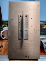
Here's a pic of the first T done and test fit. I will fire up the press for the second one, as some of these were a bit off the perpendicular. :O
Is it a bit of overkill? Probably, I could have done with 2 less holes. At the time I was going to use the same size screws, but I went to an M4 which has more beef. I left the originals as sized and the inner holes are mine and M4.
Attachments
It was the point on the through tap....
Anyway, I drilled the second one on the press and took a bit more care. I like this pattern and will use it on the second build. Next up leveling the sinks and Ts. I think I'm going to setup fences on either side of the area I need. I see no point in spending time on areas I'm not using.
Anyway, I drilled the second one on the press and took a bit more care. I like this pattern and will use it on the second build. Next up leveling the sinks and Ts. I think I'm going to setup fences on either side of the area I need. I see no point in spending time on areas I'm not using.
Attachments
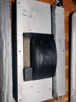
I decided to work on some lapping. I think I should have waited for the machine shop on Monday. 😛 I was rather shocked by just how bad the flatness turned out to be. I spent a couple hours on one sink and T. When I first set them together, I could rock the T like a teeter totter. It's no wonder some heat issues were found. I didn't get them perfect, but no more rocking and as much as I was willing to do. I still have the other side to do yet. The main thing is to get it close, so you don't have that thick layer of compound.
The T looks like they extruded it, but didn't come back and grind it flat. The worse part was right down the middle, it looked to be a good deal concave there.
The T looks like they extruded it, but didn't come back and grind it flat. The worse part was right down the middle, it looked to be a good deal concave there.
For the new peeps, when you use paste for heatsinks, you want tighten all the screws, wait 20mins or so and go over them again, then again. I also check them after a few heat cycles. That goes for the FETs as well. Heat and time may change the torque. I wiped all the outflow from the sinks to T. I went back and had another bead around them having being pushed out with time. There was also a good deal less torque. Hydraulics will make them feel tight, but since it isn't a sealed system, the pressure will ease as more liquid/compound is pushed out. 😉 Ideally, you only want enough to fill in the micro imperfections, you don't use it to fill warped, or bad seats. This will, for sure, create heat problems and it will cook out those larger quantities causing further heat increases.
I know most/all have been built, but if you go back, or change stuff... Also, look at the T bracket with regard to flatness to FET seating. Also, if you go the route Zen did, you could think about a thin nut, or two, on the back side of the T, so your torque in not imparted to the output board. In this way, you would keep from using the circuit board as your limiting factor when seating the FETs. Yes, it would drop the board down a bit, but I have never liked having a CB sandwich and torqued bolts. I time, it will warp the sh8t out of the board, or maybe cause cracks. I know this from working on Yamaha B2s and the like. Time, heat, and pressure......
Also, there are power switches which fit the form factor that are DBDT/DPST. In other words, no case mods needed for that part.
Also, there are power switches which fit the form factor that are DBDT/DPST. In other words, no case mods needed for that part.
Retested abs re-calibrated the TUBA board. It's been on the bench for almost two years, so I thought it prudent. The voltages were close, but I tweaked them a bit closer. Next up... re-check all of Marks boards for proper function. All were tested, but I want to go back and make sure.
I'm retesting the FE board now... is there anything I need to do before adding the output boards? I know we need to look for 1.3v across the Rs and 14v from case to ground. Anything else?
I'm retesting the FE board now... is there anything I need to do before adding the output boards? I know we need to look for 1.3v across the Rs and 14v from case to ground. Anything else?
- Home
- Amplifiers
- Pass Labs
- DIY Sony VFET pt 2 (N-Channel Build)