#98
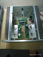
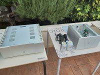
I'm very pleased to report that #98 is alive and working. I spent three nice afternoons soldering, and all last sunday cabling and putting box together.
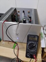
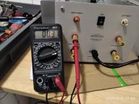
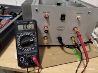
I was a bit worried during first start, but nothing strange happened. No smoke, no problem, everything measures well. Both channels adjust at 14.0v easily. AC at speaker posts is 0.3mV, both channels (with multimeter).
Now it's connected to a 12" Tannoy Dual and I can't hear any noise, even with my ear in the tweeter.
Than you Mr Pass and diyAudio Store for this wonderful amp.
Victor
I'm very pleased to report that #98 is alive and working. I spent three nice afternoons soldering, and all last sunday cabling and putting box together.
I was a bit worried during first start, but nothing strange happened. No smoke, no problem, everything measures well. Both channels adjust at 14.0v easily. AC at speaker posts is 0.3mV, both channels (with multimeter).
Now it's connected to a 12" Tannoy Dual and I can't hear any noise, even with my ear in the tweeter.
Than you Mr Pass and diyAudio Store for this wonderful amp.
Victor
Hello Víctor!!!!!
Wonderful !!!! As you know a beer and a listening session must come as soon as possible.
Regards
Miguel 🙂

Hello Víctor!!!!!
Wonderful !!!! As you know a beer and a listening session must come as soon as possible.
Regards
Miguel 🙂
Claro que sí Miguel
Of course we will have an audition, hopefully very soon. If we want, the amp can be on display at Carlos' place next 11th.
Victor
Hi,
I've read that we can add a cap on the OS board for filtering improvement. What is th e max value we could use ? I add Panasonic FK 3300µF... too much ?
I've read that we can add a cap on the OS board for filtering improvement. What is th e max value we could use ? I add Panasonic FK 3300µF... too much ?
Today is the day!!!!
Sony VFET and F5 !!
A good listening session with a beer. Regards from Spain to all forum and special thanks to Mr. Pass for make it possible.
Sony VFET and F5 !!
A good listening session with a beer. Regards from Spain to all forum and special thanks to Mr. Pass for make it possible.
Claro que sí Miguel
Of course we will have an audition, hopefully very soon. If we want, the amp can be on display at Carlos' place next 11th.
Victo
Attachments
Finally found the time to get 091 assembled! No smoke and everything tested well, heatsinks over the VFETs maxed out at 42 degrees C, pots barely needed adjusting.
But a thermal mystery….
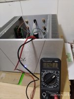
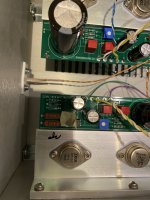
One channel is fine (temps in the 35-40 range). The other channel measured 80-95 degrees C on the body of Q3, the pcb next to it, and the bracket between IRF and Q3. The high temps are localized to the region with the masking tape in the photo, dropping to temps similar to the other channel as I move away from Q3 to the pot, caps and the resistor bodies. The 95 degrees C has me worried, but the big difference between the channels, too.
Any suggestions on what I should test or measure next?
Thanks!
But a thermal mystery….
One channel is fine (temps in the 35-40 range). The other channel measured 80-95 degrees C on the body of Q3, the pcb next to it, and the bracket between IRF and Q3. The high temps are localized to the region with the masking tape in the photo, dropping to temps similar to the other channel as I move away from Q3 to the pot, caps and the resistor bodies. The 95 degrees C has me worried, but the big difference between the channels, too.
Any suggestions on what I should test or measure next?
Thanks!
Attachments
fingerpoking , or what exact method of measuring Temp?
when in doubt, use contact sensor measuring (either standalone gadget or DMM with Temp probe )
when in doubt, use contact sensor measuring (either standalone gadget or DMM with Temp probe )
IR thermometer. Not reliable for shiny surfaces, so I used the masking tape to make a readable surface. Once the power was disconnected, the temperature dropped to equal on both sides.fingerpoking , or what exact method of measuring Temp?
when in doubt, use contact sensor measuring (either standalone gadget or DMM with Temp probe )
usually, bad contact (in circuit having significant current) is causing excessive temperature rise
anyway, we already had few cases as yours - IR showing (not actually existing) difference
that's why I said to check in any other possible way
anyway, we already had few cases as yours - IR showing (not actually existing) difference
that's why I said to check in any other possible way
Thank you for the reply! I don’t have a better way of checking the temperature, unless a meat thermometer counts. I’ll see if I can find something better locally.usually, bad contact (in circuit having significant current) is causing excessive temperature rise
anyway, we already had few cases as yours - IR showing (not actually existing) difference
that's why I said to check in any other possible way
This sounds like an incomplete thermal contact between the aluminum bracket and the main heatsink on the hot channel. The mounting screws may be bottoming out in the threaded holes on the heatsinks. Try adding extra M3 washers under the screw heads. Some of the silver thermal grease should squeeze out when the screws are tight.
A cooking thermometer will work. That is what I use, or a finger. At 80-95 degrees C, a finger will hurt on contact.
At that temperature, it is also off the Nelson Pass finger test scale:
Blimey Hot : 10 seconds hands on = 45c
Crikey Hot : 5 seconds hands on = 50c
Bloody Hot : 2 seconds hands on = 55c
X*?@! = 60c
.
At that temperature, it is also off the Nelson Pass finger test scale:
Blimey Hot : 10 seconds hands on = 45c
Crikey Hot : 5 seconds hands on = 50c
Bloody Hot : 2 seconds hands on = 55c
X*?@! = 60c
.
- Home
- Amplifiers
- Pass Labs
- DIY Sony VFET pt 2 (N-Channel Build)