Two alpha-testers posted messages here on diyAudio about their listening evaluations, after installing a prototype Theseus-PSFILT into their VFET amps. One was an Nchannel VFET amp, the other was a Pchannel VFET amp. Did that board reduce or eliminate turn-off thumps and turn-on thumps? Here are their messages.
Post #528 in this thread by member rgolan
Post #1900 in the other (Pchan VFET) thread by member HappyJack
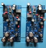
Have a careful look at the PCB photos in their posts, you'll see that PSFILT contains a bunch of fairly expensive components including almost twenty dollars worth of wire-to-board connectors.
The entire Ship Of Theseus project is still unreleased, thus the Theseus-PSFILT board is still unreleased. I sure do hope (and sure do not promise) that Theseus will be released this year.
Post #528 in this thread by member rgolan
Post #1900 in the other (Pchan VFET) thread by member HappyJack
Have a careful look at the PCB photos in their posts, you'll see that PSFILT contains a bunch of fairly expensive components including almost twenty dollars worth of wire-to-board connectors.
The entire Ship Of Theseus project is still unreleased, thus the Theseus-PSFILT board is still unreleased. I sure do hope (and sure do not promise) that Theseus will be released this year.
I'm also eager to try some of the new front end cards Mark Johnson has developed. As you can see below, the frequency response of the Sony DIY VFET has some "peculiarities" 😀
It's actually the Edcor, as my M2 has a similar overshoot / ultrasonic resonance, and my SissySIT (which uses Cinemag transformers) has none of it - totally clean square waves.
That's why I want to try a few different front ends - at least one without a transformer, and one with a different transformer than the Edcor...
I'm surprised there hasn't been more discussion about the ugly square wave distortion some of us are seeing from the Edcor transformers. NP's photos looked okay (with respect to not having the crossover notch), so I'm wondering what the issue is. Is it QC on the transformers?
Does anyone have a DPST (that's what we ending needing?) they can part with? I'm not planning on placing a digikey order anytime soon, and my stash of switches are too large. Neverthought I'd miss RadioShack 🤪
Please PM To keep the thread clean.
Please PM To keep the thread clean.
I think I remember that a member posted an amazon link to some DPST rocker switches, which he claimed were compatible with the Nchannel VFET panel cutout. Find the "anybody got a part number?" discussions about switches, and look closely. I'm 88% positive about this, i.e., not 100% .

Thanks for bringing the measurements of my DIY VFET N up again, Aleph5 ! I long wanted to write about my measurements and experiences with a different front end card.
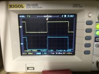
First: the resonance in the square wave really is due to the Edcor transformer. My M2 does have it also. I think it is just the way these transformers are.
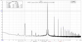
When I had my Marauder boards in the amp, the square wave looked very different. Have a look at the picture; it is almost a perfect 10 kHz square wave. Frequency response of the VFET N at -3dB is from about 5.5 Hz to about 700 kHz with the Marauder boards, with about 90 degrees phase shift at both -3dB points. The distortion spectrum looks practically identical to the spectrum with the original front ends with the Edcors. So, the resonance of the Edcors has no effect on distortion or the harmonic spectrum measured at 1 kHz. The Edcor-based amp has rising distortion below 100 Hz (seen as well with my M2 and due to the transformer in the front end), and slightly rising distortion above 10 kHz, whereas the Marauder-based amp is ruler-flat from below 20 Hz out to 20 kHz. Again, thank you, Mark, for all your work with the different front-end options, also for the DIY VFET. These are some really great cards !
Interestingly, the 100 Hz bump is the same with the original front end boards (with Edcor) and the Marauder boards (no transformer). So, no magnetic coupling / pick-up here, it's all residual PSU ripple. It looks worse than it actually is, though. As I can barely hear it with my ear at the driver of my 100 dB/W sensitive speakers, it doesn't bother me, and I will not put additional filter cards in the amp over the dual PO89ZB boards 😉.
Now to the most interesting part - how does it sound ? Well, as mentioned elsewhere already, my system with the DIY FET N with the Marauder front end to me sounds "clean, clear, and intense". Significantly more interesting, transparent, and intense than with the original front-ends.
As a comparison, my SissySIT R.3 with heroic dual-mono PSU brings to mind "quiet authority - swing - feeling - insight". Insight, as in what the musicians are doing, how they are playing together. Of all the amps I've built so far, the SissySIT still is the one that brings me closest to the music and the musicians and holds my attention the most. (Aleksandar, this is on you ! 😉)
However, I have another set of front-end boards sitting there, completely built and tested, and will try the DIY VFET with Cinemag transformers soon (same transformers as in the SissySIT) ... just need to change the boards in the amp and run it through some measurements ...
Cheers,
Claas
First: the resonance in the square wave really is due to the Edcor transformer. My M2 does have it also. I think it is just the way these transformers are.
When I had my Marauder boards in the amp, the square wave looked very different. Have a look at the picture; it is almost a perfect 10 kHz square wave. Frequency response of the VFET N at -3dB is from about 5.5 Hz to about 700 kHz with the Marauder boards, with about 90 degrees phase shift at both -3dB points. The distortion spectrum looks practically identical to the spectrum with the original front ends with the Edcors. So, the resonance of the Edcors has no effect on distortion or the harmonic spectrum measured at 1 kHz. The Edcor-based amp has rising distortion below 100 Hz (seen as well with my M2 and due to the transformer in the front end), and slightly rising distortion above 10 kHz, whereas the Marauder-based amp is ruler-flat from below 20 Hz out to 20 kHz. Again, thank you, Mark, for all your work with the different front-end options, also for the DIY VFET. These are some really great cards !
Interestingly, the 100 Hz bump is the same with the original front end boards (with Edcor) and the Marauder boards (no transformer). So, no magnetic coupling / pick-up here, it's all residual PSU ripple. It looks worse than it actually is, though. As I can barely hear it with my ear at the driver of my 100 dB/W sensitive speakers, it doesn't bother me, and I will not put additional filter cards in the amp over the dual PO89ZB boards 😉.
Now to the most interesting part - how does it sound ? Well, as mentioned elsewhere already, my system with the DIY FET N with the Marauder front end to me sounds "clean, clear, and intense". Significantly more interesting, transparent, and intense than with the original front-ends.
As a comparison, my SissySIT R.3 with heroic dual-mono PSU brings to mind "quiet authority - swing - feeling - insight". Insight, as in what the musicians are doing, how they are playing together. Of all the amps I've built so far, the SissySIT still is the one that brings me closest to the music and the musicians and holds my attention the most. (Aleksandar, this is on you ! 😉)
However, I have another set of front-end boards sitting there, completely built and tested, and will try the DIY VFET with Cinemag transformers soon (same transformers as in the SissySIT) ... just need to change the boards in the amp and run it through some measurements ...
Cheers,
Claas
Attachments
You might decide that you prefer the FFT plot (or the actual sound of the amplifier) with Marauder's slide switch in a different position. Or maybe not. Try it and see.
If you are willing to place an order, I used a CW GRSV-4021-0006 (D-K CWI494-ND) which fits fine. I think the solution to the thump problem needs a more elaborate circuit, though, and I hope to "soon" finish building one that addresses both turn on and off. I posted a schematic that addressed turn-on only, since that was all that I had heard up till then, but now the turn-off bothers me.Does anyone have a DPST (that's what we ending needing?) they can part with? I'm not planning on placing a digikey order anytime soon, and my stash of switches are too large. Neverthought I'd miss RadioShack 🤪
Please PM To keep the thread clean.
Maybe the existing relay and the right RC combination will work for you, though, along with the DPST.
The thump-suppressor circuit in the Tuba dual-regulator board (whose schematic and Gerbers are here on the Forum), eliminates both turn-on and turn-off thumps, using a transistor plus a multiplicity of diodes. It requires the DPST power switch and it requires you to actually USE the DPST switch. If you switch your VFET amp's mains on and off with a home automation system or with a power strip (either manual or WiFi activated) then you're not actually USING the DPST switch.
Nice, chide/Claas. I've got some transformerless front ends in the works, but I don't have circuit tools now to turn them into PCBs. I hope to post results soon, in any event.
I'm having a continuity issue on the switch contacts, thought I'd post before looking for a stray short.
If I measure the resistance between contacts 2 and 3 (see attachment) I get a small resistance (~1.2ohm) that seems to be slowly decreasing.
Is that expected since they are connected through some resistors and caps?
This is before powering on, before attach quick connects to the dpst switch.

If I measure the resistance between contacts 2 and 3 (see attachment) I get a small resistance (~1.2ohm) that seems to be slowly decreasing.
Is that expected since they are connected through some resistors and caps?
This is before powering on, before attach quick connects to the dpst switch.
#095 is up and running!
Has approx 1mV DC on the outputs with inputs shorted. Bias set to 14V. Gets warm but I don't need to let go of the heatsinks. Draws about 1 amp cold or warmed up.
Sounds great! No noise, hum, anything on the speakers. A really fun build.
Why are so few builders posting pix?


Has approx 1mV DC on the outputs with inputs shorted. Bias set to 14V. Gets warm but I don't need to let go of the heatsinks. Draws about 1 amp cold or warmed up.
Sounds great! No noise, hum, anything on the speakers. A really fun build.
Why are so few builders posting pix?
Great to hear (I never tire of it).
How do you like your little Fostices? I have a pair on one of my computer systems.

How do you like your little Fostices? I have a pair on one of my computer systems.
The speakers are full range, Orcas from Blumemstein Audio. Love them, but they don't go down far enough.
Blumenstein is obviously using Fostex FE83 speakers, thats what Nelson means with "Fostices" 🙂The speakers are full range, Orcas from Blumemstein Audio. Love them, but they don't go down far enough.
https://www.fostexinternational.com/docs/speaker_components/pdf/fe83rev.pdf
Our speaker choices are greatly limited by the low power output of the amp, right? Maybe in a few years I'll look into replacing them, and put them to use on my computer too.Great to hear (I never tire of it).
How do you like your little Fostices? I have a pair on one of my computer systems.
@Franz Gysi thanks for the clarification
The 'little' VFET amp punches well above its weight class. I use it with a pair of Vandersteen 2C speakers, about 88 dB.
Does a 25W Class A amp deliver a bit more? Yes, but the VFET has a wonderful sound.
Does a 25W Class A amp deliver a bit more? Yes, but the VFET has a wonderful sound.
- Home
- Amplifiers
- Pass Labs
- DIY Sony VFET pt 2 (N-Channel Build)