What are people typically driving these amps with? Mine seems very picky about the source impedance. I tried the headphone out jack from a laptop and it was terrible with all the bass rolled off. Using the line out from a soundcard yielded much better results.
The pt 2 front end is the same as the pt 1 front end. From pt 1 pdf:
"This circuit is mounted on a separate board from the output stage, and consists of a pair of complementary Jfet followers which drive the primary coil of the Edcor 600/15K step-up transformer. The Jfets are selected Toshiba 2SJ108 and 2SK370, the same chips as 2SJ74 and 2SK170 but in a smaller package, which provides for an input impedance to the amplifier of 330 Kohm and low distortion."
Perhaps the laptop headphone out has limited fidelity, with rolled off bass.
+1 on Ben Mah... never seen or experienced a problem with that front end (1st edition but same FE) and the input impedance of the FE is VERY high, so shouldn't pose a problem at all to any source I know.
Your laptop output is likely to be the limiting factor... assuming you have the original /Papa's FE of course
Claude
Your laptop output is likely to be the limiting factor... assuming you have the original /Papa's FE of course
Claude
Number 137 finally completed. 🙂
I did listen some music and first impression is very positive.
My only concern is vfet temperature. After forty minutes of playing the right channel vfet have 74 degrees celsius (165 degrees Fahrenheit) and the left 72 degrees celsius (161 degrees Fahrenheit).
Is this normal? I'm not used to it for such a high temperatures.
Attachments
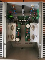
Yes. Also, the bias was tested on these units before shipping. If you want to improve that a bit you can check the bolt tighness, put a thin layer of thermal grease between the bracket/sink and make sure there's good ventilation for the sinks.
well, I'm always amused studying Papa's schematics, from any imaginable reason .... mistakes being one of them 
original, drawing mistake marked, mistake fixed, simple remedy for better AntiBigBadaBoom at speaker out
original, drawing mistake marked, mistake fixed, simple remedy for better AntiBigBadaBoom at speaker out
Attachments
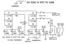
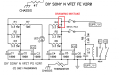
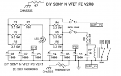
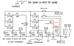
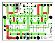
Does that mean cut the yellow pcb trace I marked in blue?mistake fixed, simple remedy for better AntiBigBadaBoom at speaker out
Attachments
My on/off switch has just failed and next week (when I get home) I was expecting to discover a silly wiring error. 
Now I'm intrigued.
Now I'm intrigued.
Does that mean cut the yellow pcb trace I marked in blue?
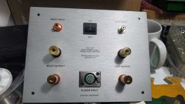
I'm in the process of assembling one Lottery amp for my dear Friend, way of paying back for valuable help he gave in some of my endeavors
Will post detailed pics, as soon I'm done, so it'll be clear how I did changes to delay circuit
In a week or so.
Silly ZM, regarding schm above - I forgot to say that - as far as I was able to see it - Pa's pcb is proper, it was just drawing mistake

No, you would cut the v+ to one of your output board.Does that mean cut the yellow pcb trace I marked in blue?
Yes, the power of suggestion was enough for me to see the schematic error on a perfectly fine pcb. Oh, and also I’m clueless. At least I asked before grabbing the Dremel.No, you would cut the v+ to one of your output board.
damn, this one is going to be extensive photo-shoot
plenty of things to change
conclusion - there is still Ton of Porridge to be eaten, for all other boys taking care of completing the package (designing things and logistics)
good intentions are not disputable, but Devil still can be found in details ......
Pa's part of package is on Pa's level, Modushop part of package is on Modushop level
few problematic slips did happen lower through the chain
just a teaser
Attachments
I'm eagerly awaiting for ZM's "build guide"!
Especially the 'AntiBigBadaBoom at speaker out' part! 🤣 I think I'll include it in my build.
Especially the 'AntiBigBadaBoom at speaker out' part! 🤣 I think I'll include it in my build.
according to my nature, I made an upfront claim of making something better than it is presently
so, as myriad times before, it'll be either All Glory, or Major Public Humiliation
(dunno - will nearly a second of relay engagement delay during power On, with immediate release during Power Off - is going to be improvement; can do more than second, but hard to squeeze-in bigger cap, without using glue-it technique )
just waiting to get tomorrow set of proper rubber feet for amp, to mount them, so I can wrap up this build
everything set, works as intended
can inform that edited delay circ is working flawlessly - no visible move of cone neither at power On nor power Off
only if you are powering it Off reluctantly, slowly operating the switch , there is movement of cone, but slow and gentle - and even that one is not audible
same behavior when leaving power switch ON, and doing power operation with mains cable of switcher - Nada during power On, gentle roll of cone with powering Off
will post plenty of pics and some text, in separate thread
maybe next evening
and yes, really dunno how delay circ operated in original, didn't tried it at all; but I'm used to change Papathings just for sport - hard to make it better, easy to make it in different way
believe it or not, just working on editing and organizing pics for said thread
few more tomorrow, while wrapping it up, and that's it
I believe everything is going to be clear and easily repeated, even without brain engagement ( my fave approach)
few more tomorrow, while wrapping it up, and that's it
I believe everything is going to be clear and easily repeated, even without brain engagement ( my fave approach)
- Home
- Amplifiers
- Pass Labs
- DIY Sony VFET pt 2 (N-Channel Build)