I added the diode across the relay coil and increased the cap to 220 uF. I left R8 the same. The relay coil connected to the ground traces are on both sides of the board so a little bit tight to get at on the component side. Totally quiet.Good news ZM.
Interested to see what delay circuit changes you made to get it to work.
Originally there was a small pop with turn on, but the turn off was annoying, wouldn't ever damage the speaker.
BDP

Have you rewired the switch as per Zm schematic too or only changed the cap and added the diode?I added the diode across the relay coil and increased the cap to 220 uF. I left R8 the same. The relay coil connected to the ground traces are on both sides of the board so a little bit tight to get at on the component side. Totally quiet.
Originally there was a small pop with turn on, but the turn off was annoying, wouldn't ever damage the speaker.
BDP
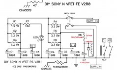
I have done a lot of project but I’m still a newbie at understanding circuit.. can someone help me understand the basic of this delay circuit?! The coil will not be energized until c7 is full? Did I get this right? What is the function of the diode added by Zm? Transient protection for the coil?
Attachments
I did the whole mod. Cut the ground traces and move the switch wiring.Have you rewired the switch as per Zm schematic too or only changed the cap and added the diode?
I have done a lot of project but I’m still a newbie at understanding circuit.. can someone help me understand the basic of this delay circuit?! The coil will not be energized until c7 is full? Did I get this right? What is the function of the diode added by Zm? Transient protection for the coil?
At turn on the voltage across C7 is minimal then starts charging at a rate determined by the time constant of R8 times C7. The turn on noise was nothing more than a pop, so maybe you want to leave C7 alone?
I should have just tried the diode and tested but since I had it apart I did the whole mod. The diode gives the relay coil a discharge path and squelches the voltage spike of the coil when power is removed.
With the mod and values I stated it is completely quiet at turn on and turn off. And I have 94 dB speakers.
Thank you for your detailed answer! On my vfet the pop on turn on is variable, sometime almost nothing and sometimes a sharp « pac ». On turn off always the same pop. I will try doing the mod one step at a time and see where it take me.I did the whole mod. Cut the ground traces and move the switch wiring.
At turn on the voltage across C7 is minimal then starts charging at a rate determined by the time constant of R8 times C7. The turn on noise was nothing more than a pop, so maybe you want to leave C7 alone?
I should have just tried the diode and tested but since I had it apart I did the whole mod. The diode gives the relay coil a discharge path and squelches the voltage spike of the coil when power is removed.
With the mod and values I stated it is completely quiet at turn on and turn off. And I have 94 dB speakers.
I've been away for a while due to health reasons. Doing some browsing to get up to speed, I see on the First Watt website there is a 2022 article entitled "DIY POWER SUPPLY FILTER / RELAY V0R0" that states that a kit will be offered through the diyAudio store. Not finding much info on this, other than Nelson's article, I'm interested in any info on whether this kit is still available. Thanks in advance for any help and guidance.
2022 article entitled "DIY POWER SUPPLY FILTER / RELAY V0R0"
Has anyone used the kit above for the N-Channel Sony VFET (pt 2). Have you @WKCox?
The part list in the article is for 24V PSU. Only minor changes are needed for a 36V PSU: C1-6 must be 50V, R10 at 120R (for a 24V relay). What about R7? It "is chosen for about 1 mA current". Is its value critical in this application?
Not critical. You can use 22k for 36v or go to 33k if it turns on too quickly for you.
Has anyone used the kit above for the N-Channel Sony VFET (pt 2). Have you @WKCox?
I now have the kit but won't have time to install it until later this year. In the process of moving.
When I lifted the top (to replace the PSU board) I noticed that the PCB traces close to the pre-installed R1 and R2 (1R5 3W) have some heavy discoloration. They look much more brown than in this picture. These resistors touch the PCB and operate above 80ºC.
I am wondering if anyone notice the same and if it is the case to replace the resistors with larger wattage and mount them with a bit of air underneath.
However, if it is safe I will leave those resistors as Pa installed them 🙂

I am wondering if anyone notice the same and if it is the case to replace the resistors with larger wattage and mount them with a bit of air underneath.
However, if it is safe I will leave those resistors as Pa installed them 🙂
Hi Claas,
I am pretty sure I have cleaned all residues from both sides. From the bottom is possible to see that the area underneath the resistors is a bit "cooked". It is just more visible where the traces are. I did not get good pictures to show it.
For sure I am not losing my sleep over this. 😉
I am pretty sure I have cleaned all residues from both sides. From the bottom is possible to see that the area underneath the resistors is a bit "cooked". It is just more visible where the traces are. I did not get good pictures to show it.
For sure I am not losing my sleep over this. 😉
prepare new resistors (be careful with value), replace them, properly cleaning old solder and applying new
take care to have at least 10mm clearance between new ones and pcb
Pa was somewhat overenthusiastic regarding working temperature of these, he's FAB No.000
take care to have at least 10mm clearance between new ones and pcb
Pa was somewhat overenthusiastic regarding working temperature of these, he's FAB No.000
Yes, but still do what Z told you either way. Any time you get a big honking resistor, it's a good idea yo give it room to breath.
Also, it's hard to tell, but I don't like the look of that one pad, it almost looks like it is slightly lifted. Be really careful if you try and remove those.
Also, it's hard to tell, but I don't like the look of that one pad, it almost looks like it is slightly lifted. Be really careful if you try and remove those.
Regarding the new PSU board kit available in the store, P1 is 1K instead of 5K as in the paper (and schematics above) and there is a 1K5 resistor in the kit that I am not sure what it is for.
Overall R7 at 22K works for me. Turn-on is barely audible on one pair of speakers and not at all on another. If you have very efficient speakers go for a larger one.
Thump on turn-off was the issue for me and now is almost gone. The best result is with P1 right in the middle. However, if I turn P1 slightly more counterclockwise the relay is not opening at all and the output stay shorted. So, no way to have a quicker shorting time at turn off. Not a big deal, again, with my speakers (90 dB).

- Home
- Amplifiers
- Pass Labs
- DIY Sony VFET pt 2 (N-Channel Build)