In your case I would do a long shaped "U" profile that wraps the pins from both sides and once heated up, it should drop out on its own. Just elevate the board and gravity should do the rest.


The best thing to do is to use side cutters and individualise each pin by cutting in between them. Then desolder one at a time.I tried to remove one with a Hakko De-soldering gun and some flux. It won't let go
Then purchase a new header.
Best of luck. Sorry it had to be the hardest to remove part!
If you buy replacements: (I've done a bit of work on the headers lately)
The round pin male header, whilst THE perfect fit for 10mm IPS standoffs (male ~3mm shroud, females ~7mm shroud) is a little pricey. There are loads of gold coated square pin alternatives that are compatible with the BOM female* - I just tested this one; 855-M20-9991445. The difference is the male shroud is 2.5mm, not 3mm, so you have to ensure a ~0.5mm air gap between the shrouds. For installation ensure only short pins go through the PCB and don't fully compress the male and female headers, then connect IPS to OPS with 10mm standoffs and ensure the 0.5mm gap is visible, before finally soldering.
If all of that is too much to get your head around, stick with the BOM male round pin. The BOM female is still the best part available for 10mm standoffs IMO.


* The BOM female 7mm shrouded receptacle can accept both round and square pins

If you buy replacements: (I've done a bit of work on the headers lately)
The round pin male header, whilst THE perfect fit for 10mm IPS standoffs (male ~3mm shroud, females ~7mm shroud) is a little pricey. There are loads of gold coated square pin alternatives that are compatible with the BOM female* - I just tested this one; 855-M20-9991445. The difference is the male shroud is 2.5mm, not 3mm, so you have to ensure a ~0.5mm air gap between the shrouds. For installation ensure only short pins go through the PCB and don't fully compress the male and female headers, then connect IPS to OPS with 10mm standoffs and ensure the 0.5mm gap is visible, before finally soldering.
If all of that is too much to get your head around, stick with the BOM male round pin. The BOM female is still the best part available for 10mm standoffs IMO.
* The BOM female 7mm shrouded receptacle can accept both round and square pins
Attachments

Yea, I appreciate it but I have enough challenges (as you've just witnessed) installing the optimal part. The replacements are US $7.44 each on Mouser. I need to order my snubbers for the transformers (I built the Quasimodo Bell Ringer) so now I've got some more parts to add to the order.Best of luck. Sorry it had to be the hardest to remove part!
If you buy replacements: (I've done a bit of work on the headers lately)
The round pin male header, whilst THE perfect fit for 10mm IPS standoffs (male ~3mm shroud, females ~7mm shroud) is a little pricey. There are loads of gold coated square pin alternatives that are compatible with the BOM female* - I just tested this one; 855-M20-9991445. The difference is the male shroud is 2.5mm, not 3mm, so you have to ensure a ~0.5mm air gap between the shrouds. For installation ensure only short pins go through the PCB and don't fully compress the male and female headers, then connect IPS to OPS with 10mm standoffs and ensure the 0.5mm gap is visible, before finally soldering.
If all of that is too much to get your head around, stick with the BOM male round pin. The BOM female is still the best part available for 10mm standoffs IMO.
View attachment 1457356
View attachment 1457350
View attachment 1457353
* The BOM female 7mm shrouded receptacle can accept both round and square pins
View attachment 1457352
Thanks for catching my mistake. I do appreciate it. I'm still learning the hard way.....
John
For a cheaper, gold plated and more readily available alternative of SIP1 see also my post from two years ago :
They work perfectly (ever since) with 10mm standoffs. Of course there is also the gap of 0.5mm, but better a small gap than compressed parts.
I have one channel up and running. I finally decided to put Q104 on the heatsink. When mounted on top of Q113 the bias dipped below 20mV after a high power episode. With Q104 on the heatsink the bias seems more stable, but I might be wrong. I also used a TTC004 (fully isolated package) instead of the recommended MJE340. Everything seems to work fine. The measured THD at 1kHz, 25W and 4ohm is below the distortion of my test setup.
By the way, I used an alternative for the male and female SIP1 connector that can be used with 10mm standoffs and which can easily be sourced from other...
By the way, I used an alternative for the male and female SIP1 connector that can be used with 10mm standoffs and which can easily be sourced from other...
Last edited:
Hi All,
2 x Wolverine V5 Input Stage boards up and running.
These are mirrored Left and Right.
Loving the build so far.
I especially like the high quality black anodised heatsinks with pcb pins from @stuartmp
They fit perfectly and saved me quite a bit of time.
Pre-drilled & tapped IPS heatsinks what luxury !
Looking good mate, very nice assembly and soldering work there for sure.2 x Wolverine V5 Input Stage boards up and running.
These are mirrored Left and Right.
Loving the build so far
Hi Guys,
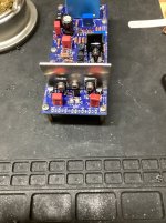
Some progress on the V5 EF3-5 OPS Build:

Some progress on the V5 EF3-5 OPS Build:
I would have thought you would place the output transistors at the bottom. Not that it makes that much of a difference.
My Wolverine V4 is playing now.

And the vented top.

And the vented top.
A couple of mirrored coils for L1 left and right

Nice, I have flipped the inductor on the right channel output boards so both inductors can be wound the same direction.A couple of mirrored coils for L1 left and right
Hi Guys,
A couple of pictures from the last few days.
Wolverine V5 EF3-5


A couple of pictures from the last few days.
Wolverine V5 EF3-5
- Home
- Amplifiers
- Solid State
- DIY Class A/B Amp The "Wolverine" build thread