
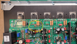
I've tried several mica parts and get the same result: middle pins of PNP beep. I've ordered another supply, maybe they are a bad batch, but I doubt it since the short pattern is so defined: NPN only, middle pin only.You don't say explicitly - but assume you mean it "beeps" when you test between middle pin and heatsink? If so, then you have an issue with the PNP's being isolated. First thing to check, is unattached to the heatsink, is there continuity to the GND, either input or power. Second would be to make sure the insulators aren't cracked or punctured.
When testing for continuity I get from PSU gnd to V+ 1.719v, V- 0.452v, output 1.55v.
Spk gnd to output 1.555v, to V+ 1,650v, to V- 0.467v
Attachments

did you removed J103? It was still populated on the previous post picture(s).
Also, measure these points in resistance mode on your DMM - that will tell you how close to a dead short (0.00) it is.
Also, measure these points in resistance mode on your DMM - that will tell you how close to a dead short (0.00) it is.
Attachments
Last edited:
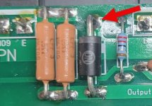
I removed J103. I'm not clear on what you want me to measure in the photo. Both 0.7r resistors are good. I discovered a short between the diode shown and the heat sink.did you removed J103? It was still populated on the previous post picture(s).
Also, measure these points in resistance mode on your DMM - that will tell you how close to a dead short (0.00) it is.
I also discovered a short between the PNP middle leg's and V-., but only that point, not V+,spk gnd, PSU gnd or output.
Attachments
good morning from Crete,
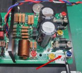
today I applied voltage for the first time,everything seems to be correct except for a voltage that shows above (on one channel)
in the voltage between TP-105 (DMM -) and the positive power rail connection I have 4.8v
and in the TP-106 (DMM +) the negative sensor on the negative rail I have 1.5v.
with transistor C3503 / A1381
all other voltages are correctTP-1 (DMM +) and TP-2 (DMM -) .... 5.0 V
TP-3 (DMM +) and TP-4 (DMM -).... 610 mV
TP-100 (DMM +) and SPK GND (DMM -)....0.01mV
on R111A and R111B it is .......0.6V adjusting to 1.4v
what ? it is wrong .
thanks
Last edited:
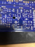
q101 installed backwards? from memory i think q101 and 102 should be facing opposing directions
Υes I have seen it, it is correct. if it were upside down,
They wouldn't turn on my LEDs
and I would not have all the other voltages correct
thanks
They wouldn't turn on my LEDs
and I would not have all the other voltages correct
thanks
Last edited:
all good now, I had put the D111 upside down.
everything now seems to work as planned ,
in the next few days I will upload photos with my build
thanks
everything now seems to work as planned ,
in the next few days I will upload photos with my build
thanks
Hi Guy's,
The Wolverine Team is excited to announce the group buy for the Wolverine V5 Special Edition! This project represents a dedication to innovation from the Wolverine team. A special thanks to @jjs (Jeremy) for his thorough analysis of the existing circuit and valuable feedback from forum members, which led to the development of a new circuit topology. This collaboration has resulted in enhancements that address low voltage start-up issues, improve clipping behavior, increase symmetrical slew rate, and reduce total harmonic distortion (THD). Extensive simulations confirm this will be the best Wolverine version yet.
The Wolverine V5 Special Edition is a significant performance upgrade over previous iterations. Our journey began in December 2023, resulting in 15 prototypes all built and tested by the team, all demonstrating incremental improvements until we have reached this final version.
Key Features of the Wolverine V5:
- Enhanced PCB Layout: Redesigned in KiCad, this new layout optimizes signal pathways and minimizes noise, leading to better performance and lower distortion levels.
- Extensive Testing Program: A shout-out to @danieljw (Daniel) for his diligent bench testing. We’ve confirmed that the Wolverine V5 offers lower distortion, exceptional sound quality and stability, reliably producing rich, detailed audio across all operating conditions.
I'll create a group buy post in the group buy section of the forum over the next few days.
Does this mean I should throw out my nearly completed 3rd Group Buy boards and start over?😀
Maybe after listening to your current build you'll be inspired to build another one. 😊 Most of the Team has 2nd GB Wolverine's and no one has plans to start over. 🙂Does this mean I should throw out my nearly completed 3rd Group Buy boards and start over?😀
Hi guys, I am very close to being able to test my EF3-4 boards V. 4. My speaker protection board and my soft start board are built. I was watching Daniel's excellent YouTube videos for the 100th time, and I remembered that cool, little T ground lift board he used. I realize you can fly wire that thing, but that little pcb keeps everything tidy. Is there a source in North America where I can buy that pcb. My understanding is that it lifts the audio ground just slightly above chassis ground while leaving chassis ground intact. Let me know if I'm thinking about this correctly.
Best,
John
Best,
John
Just order it and sell whatever you don’t use on the swap meet or keep it for future builds:Is there a source in North America where I can buy that pcb.
T-Ground: https://www.pcbway.com/project/shar...Audio_Amplifiers_Power_Supplies_766d36df.html
And
Ground Lift: https://www.pcbway.com/project/shareproject/Ground_Lift_PCB_V1_1_173beed5.html
Best,
Anand.
I am helping a fellow forum member try to get his Wolverine singing. I am testing the IPS in isolation with a +-30V bench power supply. I have connected all the extra wires and the 9.1K resisitor in parallel. When powered up, all four LED's light up. I am able to adjust the CCS for 5.0V. It also measures 29.7 VDC on the output, a small issue. Nothing is getting hot, must have already smoked. I've taken a few readings and would appreciate some help pointing me in the right direction.
Q1 base=5.9mV
Q2 base=1.7V (guessing because of the 29V on the output)
Q5&Q6 base -18.4V
Q3 base -28.8V
TP1 voltage 3.8V
TP2 voltage -1.3V
Q8 base=28.8V
Q9 base=29.3V
Q7 base=-6.3V
Q7 collector=29.9V
Q7 emitter=-14.8V
Q1 base=5.9mV
Q2 base=1.7V (guessing because of the 29V on the output)
Q5&Q6 base -18.4V
Q3 base -28.8V
TP1 voltage 3.8V
TP2 voltage -1.3V
Q8 base=28.8V
Q9 base=29.3V
Q7 base=-6.3V
Q7 collector=29.9V
Q7 emitter=-14.8V
- Home
- Amplifiers
- Solid State
- DIY Class A/B Amp The "Wolverine" build thread