Tested the leads. Aok.
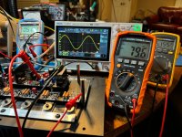
I powered up @30DCV 1A and biased to 44mV. All other measures on target.
Only question is, the POT orientation has seemed to change, e.g., yesterday I turned clockwise to maximum value, today its counterclockwise. Is there a scenario where this can happen? Haven't made any changes. I even have a Post it note "clockwise to maximum value." Today its the reverse. Last night I turned the pot many many times. Would that reverse things? Makes me nervous to return to full power.
You might need to check your carbon monoxide detectors 😛 That cannot happen from changing the voltage. You are either mixing the boards up (left right/up down etc) or mixing yourself up.
With a new detector the confusion lifted, and I've been listening to music for the last hour.
Now back to the other channel to figure out what I'm dealing with.
Now back to the other channel to figure out what I'm dealing with.

Hello Gents,
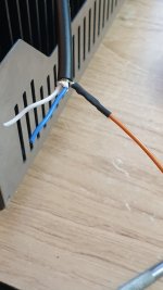
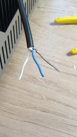
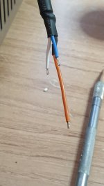
I know I've asked it before but I can't remeber or find the answer anymore🙂....One signal cable is running relatively close to the start current protector and when measuring the AC with the inputs shorted only this channel measures 0,12 mv which might be caused by the start current protector. My question is where do I connect the shield? On (-) of the signal or to the case itself?
thx in advance
Hi @wkloppen,
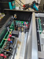
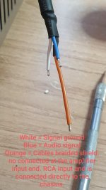
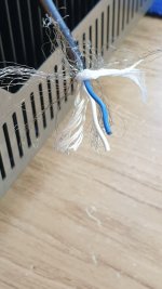
I not 100% sure what your trying to do, but you can't have a braided shield that's touching the chassis.
The cabel you want to use is Canare L-2T2S
Please refer to my photos and notes on my build album.
I not 100% sure what your trying to do, but you can't have a braided shield that's touching the chassis.
The cabel you want to use is Canare L-2T2S
Please refer to my photos and notes on my build album.
Attachments
-
 20210126_143031.jpg233.9 KB · Views: 143
 -
 20210126_143412.jpg218.1 KB · Views: 137
 -
 20240909_162214.jpg631.7 KB · Views: 132
 -
 20210126_144919.jpg249.8 KB · Views: 131
 -
 20210126_142046.jpg253.2 KB · Views: 128
 -
 20210126_142237.jpg237.9 KB · Views: 119
 -
 20210126_144232.jpg215.5 KB · Views: 130
 -
 Screenshot_20250125_205540_Photos.jpg258.8 KB · Views: 152
Thx Stuart....ordered it at audiophonics.The cabel you want to use is Canare L-2T2S
hoorah!! 😎😎With a new detector the confusion lifted, and I've been listening to music for the last hour.
Now back to the other channel to figure out what I'm dealing with.
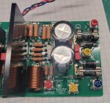
By the way, I haven't seen any examples of Wolverine builds with the power supply in a separate box. I've done that with all my class A builds and put additional capacitors on the amp side of the umbilical (which connects the power supply box to the amp box). But in the case of Wolverine, that seems unnecessary, since it already has CRC and cap multiplier filtering right on the amp boards. I like that.
I got two wolverines with two separate power supplies...

I put soo much capacitance at first, that it was stressing transformer at start and occasionally tripped the circuit breaker 🙂
For Sale Thread 'Wolverine and vFET'
I have way too many amps. Willing to part with one of my wolverines. Its in 4U modushop, with massive external power supply. Its ef3-3. Perfect sound. I will not ship it, but i can deliver within 100 miles of metro DC area. Asking $2000.
I put soo much capacitance at first, that it was stressing transformer at start and occasionally tripped the circuit breaker 🙂
Last edited:
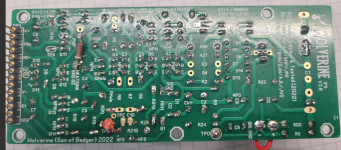
I have one channel working. I went back to my other channel. I tested it at 30DCV / .30A and all 6 Leds are on.
All readings are normal except for TP3/TP4 which should be north of 600mV but only shows 105.4mV. The other abnormality is I can't move R111A/R111B off of 719mV. I can't increase it or decrease it.
I have double checked all parts for correct placement and that they are functioning.
Something is amiss. Assume with all Leds working that indicates no issues with the transistors? Never say never but I am very careful to ensure correct deployment of each one.
Attachments

High res top down photos of the boards please, also 26V(DC?) on the output?? 😳
-26.82DCV is what the DMM showed. must have set the leds up wrong.
See photos and thanks.
See photos and thanks.
Attachments
-
 2025-01-27_ISP end.png1.1 MB · Views: 139
 -
 ISP rear.png2.1 MB · Views: 493
 -
 2025-01-27_output right end.png1.2 MB · Views: 126
 -
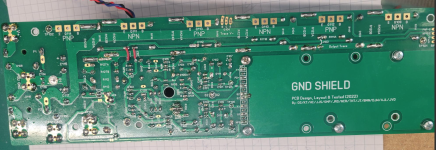 2025-01-27_output rear.png1.7 MB · Views: 240
 -
 2025-01-27_output full view.png1.7 MB · Views: 325
 -
 2025-01-27_Output board mid.png1.3 MB · Views: 227
 -
 2025-01-27_output 2nd mid.png1.3 MB · Views: 227
 -
 2025-01-27_ISP.png1.3 MB · Views: 128
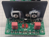
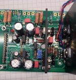
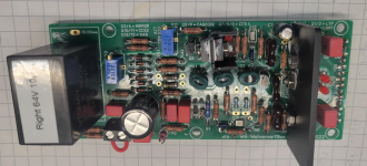
clean this up - potential short between c10 and TPC
This V+ fuse gone? (thanks @stuartmp)
Remember when you are using a bench/lab power supply, it shows the voltages it is outputting, and also the CURRENT that is flowing through each rail. If one if those rails is at 30V but 0.00A , you have a blown fuse. If you have a short somewhere the bench supply voltage should tank to 0 or just above it and the current will be maxing out at what you've set it. (someone will correct me here, I dont use a bench supply but instead a Variac with DC ammeters on the rails of a spare small linear PS setup)
Either way - the speaker output should read 0VDC ideally, or +/- 100mV max so +0.1VDC or -0.1VDC max. The 100mV offset is trimmed back to 0.00 with r25 later. 26VDC means something very wrong.
Last edited:
Are you using additional caps on the amp side of the umbilical? Seems to me it's not needed due to the onboard CRC and cap multiplier, but I'd love to have some confirmation.I got two wolverines with two separate power supplies...
Most bench supplies allow you to set overcurrent at an owner selected level. When it reachs that level it switchs off that supply, or tripps.If you have a short somewhere the bench supply voltage should tank to 0 or just above it and the current will be maxing out at what you've set it.
Modern supplies - yes, but not all. Older power supplies may not. Those only shut down once you reach the safety limit for that power supply.
Ok. Both fuses are working. Cleaned up - potential short between c10 and TPC. Speaker output is an issue. Got it. ThanksView attachment 1413721
clean this up - potential short between c10 and TPC
This V+ fuse gone? (thanks @stuartmp)
View attachment 1413723
Remember when you are using a bench/lab power supply, it shows the voltages it is outputting, and also the CURRENT that is flowing through each rail. If one if those rails is at 30V but 0.00A , you have a blown fuse. If you have a short somewhere the bench supply voltage should tank to 0 or just above it and the current will be maxing out at what you've set it. (someone will correct me here, I dont use a bench supply but instead a Variac with DC ammeters on the rails of a spare small linear PS setup)
Either way - the speaker output should read 0VDC ideally, or +/- 100mV max so +0.1VDC or -0.1VDC max. The 100mV offset is trimmed back to 0.00 with r25 later. 26VDC means something very wrong.
- Home
- Amplifiers
- Solid State
- DIY Class A/B Amp The "Wolverine" build thread