I recommend that you go back to checking each board individuallyOk. Both fuses are working. Cleaned up - potential short between c10 and TPC. Speaker output is an issue. Got it. Thanks
The AC noise is fully gone....thx for the cable tip!The cabel you want to use is Canare L-2T2S

Hi everyone,
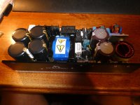
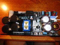
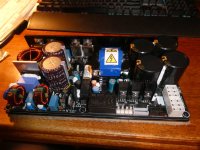
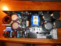
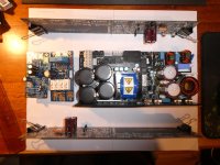
Today I received the MicroAudio Cobra-S2 SMPS! I attached some photos to show what a nice piece of technology it looks like.
Although I ordered the Cobra-S2 with +/- 70v rails voltage, and 24V standby and auxiliary power supply, there is no documentation included whatsoever how to install the thing. Online there is only a 14-page datasheet and a *.step-file, whatever that is.
Has anyone on this forum bought and installed this SMPS yet and can they give me some pointers?
E.g. do I need more connectors, what gauge wiring, etc? I there a drill pattern to put it in a case?
Cheers,
Wouter
Attachments
-
 P1030606.JPG437 KB · Views: 120
 -
 P1030607.JPG447.8 KB · Views: 122
 -
 P1030608.JPG479.1 KB · Views: 120
 -
 P1030609.JPG374.1 KB · Views: 121
 -
 P1030610.JPG491 KB · Views: 116
 -
 P1030611.JPG459.7 KB · Views: 123
 -
 P1030612.JPG549.1 KB · Views: 119
 -
 P1030614.JPG385.9 KB · Views: 120
 -
 P1030615.JPG322.7 KB · Views: 120
Datasheet is here for the electrical side, https://micro-audio.com/store/wp-content/uploads/2022/05/COBRA-S1-1.pdf and the .step is a 3d model of the thing which is all I can find for the drill pattern.
I made a mockup made from a few A4 sheets of paper with the dimensions of this case and it looks like everything fits, even with 2 auxiliary boards. As the Cobra S2 has its own soft start circuit, the external soft start board is not really necessary. Instead of that I am planning to utilise a T-ground and a ground-lift board. The speaker protection board will still be useful though.Hi everyone,
Did anyone buy and use the new Modushop "Mini Dissipante 5U 400mm 10mm SILVER front panel - 2mm aluminium covers and 3mm rear panel" yet?
It seems to be compatible with the Wolverine heatsink drilling mod.
There are no pictures yet: https://modushop.biz/site/index.php?route=product/product&product_id=940
Attachments

all drill patterns and connector information found in the hypex smps1200 documentation, as it is the same as that smps manufactured to plug and play with the same amps.
@Mainframe, so you're saying the Hypex SMPS1200 series has the same specs and footprint as the Cobra S2?
Shame they are not offering a +/- 70V option.
I read the posts by Plasticator, who has the same configuration as I am building (EF3-4 & Cobra S2), so I will ask him for advice as well.
Cheers,
Wouter
Shame they are not offering a +/- 70V option.
I read the posts by Plasticator, who has the same configuration as I am building (EF3-4 & Cobra S2), so I will ask him for advice as well.
Cheers,
Wouter
Micro-Audio Cobra S2 does not share any physical dimensions as the Hypex SMPS1200Axxx.
Cobra S2 is larger.
Cobra S2 is larger.
Also @stuartmp made and measured a coil - shown in his photo cache here --> Stuartmp wolverine build guide photos


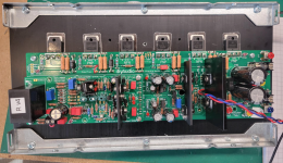
I built a new ISP board and conducted the initial power up test with my Rigol @ 30DCV 0.3A without the output transistors.
Everything went according to the defined measurements, biased at 700mV, etc.
I installed the output transistors and tested for continuity before soldering. All good.
I soldered the transistors and tested for continuity and all three middle pins of the PNP transistors beeped. I removed one of them and tested it and its working.
Given the pattern of the shorts, is a starting point to think about the likely issue?
Attachments
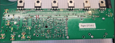
You don't say explicitly - but assume you mean it "beeps" when you test between middle pin and heatsink? If so, then you have an issue with the PNP's being isolated. First thing to check, is unattached to the heatsink, is there continuity to the GND, either input or power. Second would be to make sure the insulators aren't cracked or punctured.
It looks like you have temporary J103 still installed in your picture. I believe that should be removed when you install the transistors.
Wait ignore my last comment if you were getting shorts from Heatsink to any transistor pins. They should never beep short. I thought you meant you had short beeps when testing collector - emitter - base pins of one PNP transistor. Sometimes you will get a momentary short there that will clear within a few 100ms.
You will always get a beep between collectors OR emitters OR bases of same sex transistors as they are connected in parallel.
Also, these arent cracks in the plastic housing of these transistors??

You will always get a beep between collectors OR emitters OR bases of same sex transistors as they are connected in parallel.
Also, these arent cracks in the plastic housing of these transistors??
- Home
- Amplifiers
- Solid State
- DIY Class A/B Amp The "Wolverine" build thread