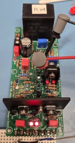
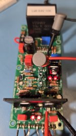
Alright, working on a second IPS in isolation. All connections in place with 9.1K in parallel. Powered by +-30V bench supply. Powers on, all four LED's light up, able to adjust 5V on CCS, able to adjust offset to 0mV. The problem is I only have 11mV across TP3 and TP4. this should have about 600mV. What should I be looking at here?
Yep, second board up and running. For anyone else doing IPS isolated testing, you get about 2.7Vpp with a 100mVpp input. One more to go, then test the output boards.
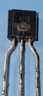
Yes, Q10 was fried, couldn't see it. That was all that was wrong on that board.
I have three identical IPS boards. They all pull 13mA on the positive rail and 17mA on the negative rail. They are being powered in isolation from a 30V bench supply. My question is: two of the boards D12 and D3 LED's are nearly as bright as D10 and D11 LED's. The third board, D12 and D3 LED's are way dimmer. I did measure the voltage on Q5 and Q6 bases and it is -2.9V on the dim board, -3.0V on the two bright boards. Everything else checks out on all three boards, including producing a nice 2.7Vpp output from a 100mVpp input. Am I grasping at straws, see the photos.


If everything else checks out as per the build guide, it could be the leds themselves or the low voltage conditions. Measure across R6 and see how close to 1.6mA you are.Am I grasping at straws
Last edited:
good morning .
first tests and everything works as planned,
My cold is small SK 93 150 SA Fischer,
with the temperature stopping at 40 degrees Celsius in a state of rest after 1 hour
I think I'm fine
first tests and everything works as planned,
My cold is small SK 93 150 SA Fischer,
with the temperature stopping at 40 degrees Celsius in a state of rest after 1 hour
I think I'm fine
These have a reasonable good safe operating area and relatively good thermal performance due to the package.
Also some people have a big stock of these to use up and they are certainly nice transistors.
However they are obsolete and you have to drill twice the holes.
MJL4302/MJL4281 offer similar performance with half the holes to drill and they are stocked currently.
- Dan
Also some people have a big stock of these to use up and they are certainly nice transistors.
However they are obsolete and you have to drill twice the holes.
MJL4302/MJL4281 offer similar performance with half the holes to drill and they are stocked currently.
- Dan
Regarding the new boards, the majority of changes have indeed been made to the IPS board. There have been a few added components to the output stage board to prevent minor oscillation under extreme conditions, which are not typical during regular listening. These conditions were observed during stress testing with very low impedance loads below 4 ohms and extreme clipping conditions (around 4Vpp). In these situations, the pre-drivers can saturate and the Ft drops (The transistors slow down), potentially causing very minor oscillation as they come out of clipping and return to normal operational conditions.Regarding new boards. Sounds like the majority of changes are on the IPS board. Since they are easily changable, have you condidered making only the new IPS boards available. That is, if they are compatible with the old boards.
While this scenario is highly unlikely during listening, we felt it prudent to add these protective components. To answer your question, yes, it is possible to upgrade only the IPS board, and you will still benefit from the all other improvements listed in my original post regarding the V5 boards.
I have 691uA across R6, so something above it must be wrong. I'll look at the divider R27 and R3 first, then may have to go to Q7.If everything else checks out as per the build guide, it could be the leds themselves or the low voltage conditions. Measure across R6 and see how close to 1.6mA you are.
I've got .9V and 2.5mA on the emitters of Q1 and Q2. I also have -2.9V on the bases of Q5 and Q6. I think these two LED's are a different model. We are going to order a set of TLHK44R1S2's and go from there. Pretty sure it is working right now, just not getting enough current through LED's. This might take care of itself with a higher voltage on the rails, but aren't going to chance it.
- Home
- Amplifiers
- Solid State
- DIY Class A/B Amp The "Wolverine" build thread
