Perfect!
Also read from Keysight and other manufacturers. DSO's sample the signal, and some have significant "blind time". You have to be careful. Also, preserving waveshape means you have to have 4x the sampling rate as the signal frequency minimum. I would only use a 100 MHz DSO for a 20 MHz waveform. An analogue scope doesn't have any "blind time". You still need 4 ~5 x the frequency overhead.
Also read from Keysight and other manufacturers. DSO's sample the signal, and some have significant "blind time". You have to be careful. Also, preserving waveshape means you have to have 4x the sampling rate as the signal frequency minimum. I would only use a 100 MHz DSO for a 20 MHz waveform. An analogue scope doesn't have any "blind time". You still need 4 ~5 x the frequency overhead.
Keysight has a good 101 course on oscilloscopes on there site. Registering is required, but can be done free.
https://www.keysight.com/gb/en/learn/course.oscilloscopes-101-deep-dive.html
However considering your current level of knowledge on electronics and amplifier design, an oscilloscope will be of limited use. And ones you have raised your knowledge to the level needed for the oscilloscope to be useful, you can likely repair the amp without a scope.

You still need an oscilloscope for basic things, like gross distortion, following a signal and oscillation. It is a very basic instrument.
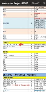
My IPS boards are version 3.8. In the notes to the BOM dated May 22, 2024 I see that diodes D13 and D14 were added. But they are not actually in
the BOM. I see where they go on the pcb. Am I correct in assuming that they are 1N4148/1N914 diodes?
I am using this BOM because it was the one closest to the release of the 3rd Group Buy boards. If I should be looking at something else that is updated please let me know.
Many thanks,,
John
the BOM. I see where they go on the pcb. Am I correct in assuming that they are 1N4148/1N914 diodes?
I am using this BOM because it was the one closest to the release of the 3rd Group Buy boards. If I should be looking at something else that is updated please let me know.
Many thanks,,
John
Would you please guide me on how to test boards in isolation?
I will retest the reassembled board on a bench first to check again for values, since it is easier than in the enclosure then proceed to do tests on each board as suggested here before.
I will retest the reassembled board on a bench first to check again for values, since it is easier than in the enclosure then proceed to do tests on each board as suggested here before.
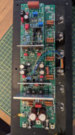
Ok so I put everything back on heatsink.
Checked output resistance of negative rail:
The fuse was blown.
After replacing it all values above required 10k ohm.
Edit: when I was working on dac I swapped signal and ground output wires by accident, could it be the cause which tipped a somewhat malfunctioning channel over the edge?
Checked output resistance of negative rail:
The fuse was blown.
After replacing it all values above required 10k ohm.
Edit: when I was working on dac I swapped signal and ground output wires by accident, could it be the cause which tipped a somewhat malfunctioning channel over the edge?
Last edited:
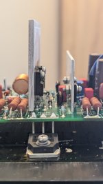
So should I go back a few steps and desolder output transistors and put jumper in place then check everything?
They were tight enough to keep transistors flush against heatsink.
Definitely not loose
Do you suspect this could be a problem?
Definitely not loose
Do you suspect this could be a problem?
Ok. Will do it now.
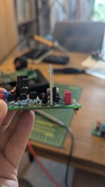
I did check in the compare bothe boards now in the diode mode if values any different. Look the same.
Looks like 100 l% to know for sure is to desolder them.
I did check in the compare bothe boards now in the diode mode if values any different. Look the same.
Looks like 100 l% to know for sure is to desolder them.
Probably not, but its always best to start at the obvious. Did you have any other transistors tightened the same way when you tested? When you power these up they should ALL be tightened correctly, or even torqued if you have the means to do so.
- Home
- Amplifiers
- Solid State
- DIY Class A/B Amp The "Wolverine" build thread