mainframe99 to the rescue! Thank you Buddy as you answered all my questions. No I didn't buy output transistors yet. But now I am close to unleashing a massive Mouser order. I know I'll forget something, but I'm trying to minimize multiple shipping chargeSee here on matching : Post 3476
Hope you didn't buy loads of these. Unlike sankens and toshibas, these will be crazy close 1-2% same type and about 5% between types, there is no need to worry.
This is good. Any builder can do wolverine with just a multimeter.
for Q1 2 3 4 5 6 I would suggest 50 min each would likely get you all the matches you need.
As linked above. Up to you. Only Q1 2 3 4 critical. I've done amps matching only these, and the amps amazing.
Yes, as I mentioned previously, you will need to drill and tap Q103, 107 and 108 holes 🙂
Thanks again,
John
Do you have a BOM for this board? What about instructions on how to use it?I have 5 of the transistor matching boards available that are based on @anatech's design. $13 shipped in the lower 48 States of USA. PM me if interested. I can ship outside the lower 48 but it will cost more. I have used the board to match transistors on a numner of projects and it works EXTREMELY well.
Thanks,
John
No BOM, the parts are labeled on the board and discussed in this thread: https://www.diyaudio.com/community/threads/matching-transistors-measuring-the-results.307138/latest Operation onf the board is also discussed.

From memory and I maybe wrong. One of the members posted a bom they created in this thread back when @anatech posted about this early in this thread. Maybe do some searching.No BOM, the parts are labeled on the board and discussed in this thread:
Check post #201 it has a bom attached and #216 has an image of the completed transistor matcherNo BOM, the parts are labeled on the board and discussed in this thread
I have one as well. It's just one of those tools you must have if you are experimenting a lot. I found that you have to perform the maintenance once in a while to insure it's always in standby condition...and the maintenance is simple.I bought a Hakko FR-301 about 2 years ago and it has been an awesome. I had issues with applying heat and then quickly putting the sucker in position. This thing works wonders. Once in while I'll need to add solder before removing it, but very efficient. Well worth the expense.
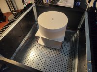
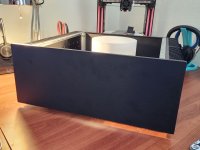
Out of morbid curiosity and the inability to leave well enough alone, I have managed to (sort of) stuff two Toroidy TTSAS0600's stacked in a 4U chassis. It's a little janky but I do have another pair of boards I'll eventually buy a 5U for and these will likely move to that and I'll buy smaller ones for this one. Any safety reason why I shouldn't do this? Is 5mm clearance beneath each transformer enough for wiring? I checked and I have enough clearance from the top of the chassis in case I need a little more room for wires. Should I just purchase two standard Audio Grade ones instead? Looking for some feedback.
Attachments
Thanks, I knew I couldn't be the first to try it. I'll take a look through the thread for it now.
It may look cool with toroids mounted on top. Like in tube amps. Especially with stainless steel shine.
Plus less possibility for hum. The top cover likely needs reinforcement.
Plus less possibility for hum. The top cover likely needs reinforcement.
I thought about doing that, if I could sit them flush with the lid with two holes cut out I think that would look pretty cool.
So I managed to desolder these.I don't have alot of time right now but maybe start with pulling out and checking Q102
R113
D116 or R131
If the checkout please pull out and check Q105, Q106
We can go from there.
Used mm and transistor checker.
D116 - mbr1100: uf 266 on checker, mm shows 0.242v in diode mode. Reverse no continuity
Resistor is 0.95r
Q102, a1381, recognised as pnp, hfe 144
Q105 and 108 (3503, 1381) both 142 hfe, mm test on legs shows 0.666 v across all, pnp npn respectively
I got an old DSO scope last week, which should be enough to test things, but it will take time to learn how to use it. Besides, I need a signal generator too, so I will probably opt for a cheap Chinese one.
Ok, so all that checks out ok. Can you please post an link to your original description of the problem?So I managed to desolder these.
Used mm and transistor checker.
D116 - mbr1100: uf 266 on checker, mm shows 0.242v in diode mode. Reverse no continuity
Resistor is 0.95r
Q102, a1381, recognised as pnp, hfe 144
Q105 and 108 (3503, 1381) both 142 hfe, mm test on legs shows 0.666 v across all, pnp npn respectively
My suggestion now is to test the IPS and OPS independently as shown in the build guild to help narrow down where the problem is.
One side was getting hot around q112 and q110.TP1 to TP2: 5.95 V (decreasing slowly)
TP3 to TP 4: 0.196V
TP105 to V= is 1.35V
TP106 to V- is 51.35V !!!
Something is seriously wrong
It was getting hot, even idle, when nothing was connected. One channel amplifies the signal much more than the other one.
I started checking the board as in the build guide and the results shown above.
I can check all values on the PCB against the working channel to see anything peculiar, just to start with.
I have a bench power supply and oscilloscope (but no idea how to use it yet) and should be getting a simple waveform generator this week.
Actually, a DSO operates differently than an analogue oscilloscope. It has some functions an analogue doesn't have, but for what you are doing, an analogue scope is vastly superior.
You have to be careful about the settings on the DSO. It may not show a signal that is there, or an aliased signal. In other words, it doesn't always show you what exists. It can lie.
I've had a number of DSO's, and ton's of analogue scopes (bought many of them for my service shop). I started with a 500 KHz tube recurrent sweep scope (no triggering). Progressed through various scopes, some pretty expensive. Then hit DSO's which were even more expensive. To give you an idea, my current main scope is a Keysight MSOX3104T, but for many analogue signals, my Philips PM-3070 or PM-3365A are both much better, especially for CD eye patterns. I keep the analogue ones around because sometimes they are simply the best tool for the job.
An analogue scope is much easier to get the truth from. So for someone starting out, analogue is by far the best way to go.
- Home
- Amplifiers
- Solid State
- DIY Class A/B Amp The "Wolverine" build thread