
What if I am going to connect whole channel assembly to a bench psu and limit current to see what happens?
Maybe stupid question...but are those power transistors insulated from heatsink? I see no keratherm sticking out.Nope 🙂
The amplifier had been completed by a fellow site member here because I ran into a problem I could not fix. It was working perfectly fine with only one channel gradually getting warmer over time (5 c difference in the end).
Then, me being me, I connected the DAC output wrong, effectively reversing the signal and ground leads.
This made the left channel work somewhat loudly, but the right one was over the top. I disconnected everything straight away, and after that the right channel was making a grunting sound for maybe 3 sec.
I did not spot a blown fuse until today, but when I was making measurements between the test point and the output of the negative rail, it showed -51.8V.
I am not sure how that would be possible if the negative rail fuse was blown.
Basically, without other suggestions, I will probably desolder output transistors and go two steps back, as in the build guide, to start troubleshooting.
Hi Vox,
Oh, no - sorry to hear you've got further problems.
Apart from the 'soak' time required as per the build guide recommendations for adjusting the bias, etc., I didn't run it for any appreciable length of time after I'd repaired it for you - I was just pleased for you that it was working again and I could arrange to get it back to you without delay so you could start to enjoy it! As I recall I left it merrily playing some music for around 15-20 minutes, so as to provide absolute confirmation it was all working correctly, and I didn't see or suspect anything untoward during, or at the end, of that time.
However, you've said that it was working fine up until your 'DAC issue', so the evidence does suggest something must have happened then, doesn't it?
Hope you get it sorted.
All the best,
Richard
Use the build guide to test the input boards seperately first, then move on the to the outputs. Your - reading probably had the leads reversed.
No problem Richard. Always be thankful for your help!Hope you get it sorted.
As you know, I needed to replace all the O/P trans on the faulty channel - do you know if that was the one displaying the up-creep in temp, or was it the other channel that I hadn't needed to touch?
Just curious - wondering what may be the reason for the slow temp increase you saw ....
Just curious - wondering what may be the reason for the slow temp increase you saw ....
The one you fixed.
Input board has V-, V+,ND -, ND +, G1 and NFB.
Can someone describe how to hook up this board in isolation ( I have a PSU capable of bipolar output), voltage settings and current limit?
Thanks
Input board has V-, V+,ND -, ND +, G1 and NFB.
Can someone describe how to hook up this board in isolation ( I have a PSU capable of bipolar output), voltage settings and current limit?
Thanks
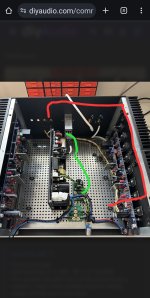
After fixing my burnt Zobel network, i assembled one channel again today.
After slowly adjusting bias and offset i decided to connect my scope, DAC and test speaker.
Unfortunately the channel is quite noisy. What i believe to be 50Hz noise is very audible from the speaker 🙁
I have a feeling that it might be due to bad wiring. Could one of you guys in here maybe confirm if my wiring scheme is bad?
Thanks a lot!
Page 51 version 41 build guide.The one you fixed.
Input board has V-, V+,ND -, ND +, G1 and NFB.
Can someone describe how to hook up this board in isolation ( I have a PSU capable of bipolar output), voltage settings and current limit?
Thanks
Do you have a current limiting supply?So should I go back a few steps and desolder output transistors and put jumper in place then check everything
What size fuses are you runningThe fuse was blown.
After replacing it all values above required 10k ohm.
That shouldn't matter D1 & D2 will conduct and limit the input voltagewhen I was working on dac I swapped signal and ground output wires by accident, could it be the cause which tipped a somewhat malfunctioning channel over the edge?
I don't like the idea of spring washers there. By the time you tighten them your probably creating a point load on the transistors which is higher that necessary. I'd remove them completely.Why are these not tightened?
Please follow the trouble shooting section of the build guild and give us an update
1. Watch Daniel's wiring video.I have a feeling that it might be due to bad wiring. Could one of you guys in here maybe confirm if my wiring scheme is bad?
2. You don't have the safety ground from your input module connected to the chassis. It should be right near the input module.
3. Turn the ground lift around and connect the safety ground terminal to the same point on your chassis from above.
4. Run your output wires on the other side of your board, not next to the sensitive negative feedback path.
Good luck 👍
Attachments
Thanks a lot Stuart!1. Watch Daniel's wiring video.
2. You don't have the safety ground from your input module connected to the chassis. It should be right near the input module.
3. Turn the ground lift around and connect the safety ground terminal to the same point on your chassis from above.
4. Run your output wires on the other side of your board, not next to the sensitive negative feedback path.
Good luck 👍
Will try your suggestions tomorrow.
It amazes me how important good wiring actually is 🙂
Are you saying that the fuse that blew was 2A if so that's not large enough. Please check page 2 of the bom for a suitable fuse.2A fuse
Then, me being me, I connected the DAC output wrong, effectively reversing the signal and ground leads.
This made the left channel work somewhat loudly, but the right one was over the top. I disconnected everything straight away, and ....
Have you checked that the DAC is not damaged?
Shorting its signal output to amp ground is not a good thing and then subsequently reconnecting this to the amp could have sent high enough uncontrolled frequencies and/or voltages to blow amp fuses and perhaps more. Do you have a sig gen? - if so use it.
- Home
- Amplifiers
- Solid State
- DIY Class A/B Amp The "Wolverine" build thread