
^nice, clean.
Thanks Daniel, and after aligning measurement setups, I got noise at similar levels +0/-5uV to your videos, so I know I'm objectively in on the same playing field.
It would appear to me, at least with these excellent Toroidy traffos, there is little noise penalty to having both boards with transistors facing up. In my amp the board with the IPS closest to the transformer shows about 5-7uV more noise at 50hz than the other, while the board with the IPS closer to the caps seems to have more rectifier 100/150hz switching noise and harmonics. But this is really looking down into the weeds. This could also be the lengths of the DC power cables being longer resulting in slightly more inductance between the power res caps and the rail caps - ref. Bob Cordell's Burning amp speech.
Hi Mainframe99,
Glad you have a comparable result, here is an FFT from yesterday idling on my work bench with shorted input running from a basic linear supply. This build is not in a chassis and has relatively long psu leads.
.png")
Glad you have a comparable result, here is an FFT from yesterday idling on my work bench with shorted input running from a basic linear supply. This build is not in a chassis and has relatively long psu leads.
Yep very similar to what I’ve had out of chassis.
Monoblock is the best way, no doubt. But stereos still certainly good enough.
Monoblock is the best way, no doubt. But stereos still certainly good enough.
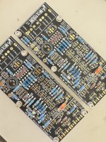
I'm glad to see your amplifier is progressing and your doing a super neat job.Got started on the IPS boards yesterday.
I encourage other builders to post their progress photos as well.
Just curious if there were any other opinions on the drivers, C4883a and A1859a (120 MHz and 60 MHz) vs C3298b and A1306b (100 MHz and 100 MHz). Which would be considered the better or more desirable to use?
Dan
Dan
There is very little discussion on the C3298B and A1306B parts. I am not familiar with them. The data sheets look like they could be a fit for an alternative driver, but wait for build team to reply. Another concern is the matching compensation parts C4/C5/R20. My opinion, they look ancient. I would be concerned about them being genuine or as performant as they may have been off the assembly line. The C4883A/A1859A are a stellar modern part here for ~70VDC rails. Shame they have been discontinued. That said, my recent build I went with MJE15034/5 and it sounds sublime.
There is very little discussion on the C3298B and A1306B parts. I am not familiar with them. The data sheets look like they could be a fit for an alternative driver, but wait for build team to reply. Another concern is the matching compensation parts C4/C5/R20. My opinion, they look ancient. I would be concerned about them being genuine or as performant as they may have been off the assembly line. The C4883A/A1859A are a stellar modern part here for ~70VDC rails. Shame they have been discontinued. That said, my recent build I went with MJE15034/5 and it sounds sublime.
They are a bit older, purchased about 20 years or so ago in Japan. They are absolutely authentic. I’ve privately discussed with a couple people and it is confirmed they’d have no problem driving 4 pairs of outputs on 71v rails, so they’re up to the task I know. I was just maybe looking for a comparison. What I have been able to find on them as far as discussions is that they’re described as one of the best driver pairs made, but I’ve never seen a direct comparison made, so just curious if anyone had an opinion. I know Onkyo liked using them, they were used as drivers in the M-504 (I have an M-504 sitting next to me), the M-508 grand integra as well as a several others of theirs, and I know that Yamaha used them in several of their upper end power amps and integrateds like the M-80 and MX-1000. They were used by Luxman quite a bit too in their power amps. They were also popular with QSC for pro stuff. Mostly what your see are the plain “C3298” or “C3298A” which are 160v and 180v parts. The “C3298B” is just the 200v version. So you’ll see more discussion regarding the others.
So I know they were pretty widely used and that they are looked highly upon. I guess I’m mostly curious about a pair of drivers with matched Ft of 100 MHz vs a pair with mismatched of 120 MHz and 60 MHz. Obviously the pair with the mismatch works fine, but just wanted some thoughts on it.
Thanks
Dan
Last edited:
Question for Design Team: IPS board mica caps at C5 and Chelp are the same value (470pF 500 V), but the tolerance on one is 1% and is 2% on the other. Can I use the 1% tolerance mica cap in both positions? Or is there some other attribute that is different but crucial on the data sheet. If there is, I don't see it.
Thanks,
John
Thanks,
John
2% for either position is fine.IPS board mica caps at C5 and Chelp are the same value (470pF 500 V), but the tolerance on one is 1% and is 2% on the other
5% for chelp is fine.
This can also be used for chelp.
Multilayer Ceramic Capacitors MLCC - Leaded 470PF 50V 5% 5.0MM
Mouser 81-RDE5C1H471J0M1H3A
You can use 1% in both positions if you like. Pays to remember if you have the means to measure them, 5% is the binning for the fixed final value and doesn’t indicate any kind of “drift” so you can have a 5% part that measures bang on, that’s a 0% part.
Thank you stuartmp!
And thank you mainframe99 for the information.
I'm building my parts order and for some reason the 1% mica caps are significantly less expensive than the 2% caps.
John
And thank you mainframe99 for the information.
I'm building my parts order and for some reason the 1% mica caps are significantly less expensive than the 2% caps.
John
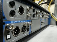
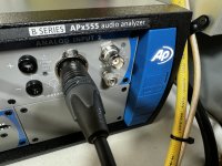
The new measurement setup. It will be very interesting to see what the Wolverine and various combinations of it actually measure. I have also not forgotten about the Balanced input module, but over the last couple months I have been pretty busy and had no time to finish it off, and I was also waiting on finalizing the purchase of the AP so I can get proper measurements of the buffer.
Attachments
For the IPS R7/8 would these resistors be OK? https://www.digikey.co.uk/en/products/detail/yageo/MFP-25BRD52-220R/2058809
While those resistors are suitable and would probably work just fine. We recommend 1/2W for increased stability and long term reliability.For the IPS R7/8 would these resistors ok?
Those 1/4 watt resistors are a large body resistor for 1/4 watt rating and will work without problems.For the IPS R7/8 would these resistors be OK? https://www.digikey.co.uk/en/products/detail/yageo/MFP-25BRD52-220R/2058809
🤔 that the CD15 series? where at?Thank you stuartmp!
And thank you mainframe99 for the information.
I'm building my parts order and for some reason the 1% mica caps are significantly less expensive than the 2% caps.
John
WOW 😎 What was the margin on those heatsinks?? jk. Very nice.The new measurement setup. It will be very interesting to see what the Wolverine and various combinations of it actually measure. I have also not forgotten about the Balanced input module, but over the last couple months I have been pretty busy and had no time to finish it off, and I was also waiting on finalizing the purchase of the AP so I can get proper measurements of the buffer.
Hope you make the most of that bad boy and contract out!
HAHA, yeah right. Not even close to making the deposit on that AP
- Home
- Amplifiers
- Solid State
- DIY Class A/B Amp The "Wolverine" build thread