600 or 625VA doesn't matter.
Toroidy could be an option: https://sklep.toroidy.pl/en_US/c/Toroidal-transformers-AUDIO-GRADE/75
Supreme Audio Grade V2 is too tall above 400VA.
Toroidy could be an option: https://sklep.toroidy.pl/en_US/c/Toroidal-transformers-AUDIO-GRADE/75
Supreme Audio Grade V2 is too tall above 400VA.
Figured that'd be the case. I wasn't sure if Toroidy ships to the US so I ruled them out but I'll send them an email anyway. Thanks!
Nothing wrong with centre tapped transformers, or transformers a little higher in current. You want to keep the voltage close. Just as a note.

Greetings fellow builders!
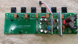
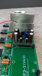
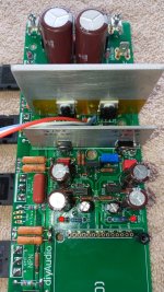
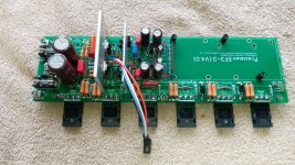
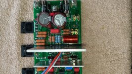
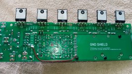
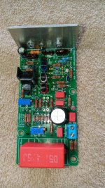
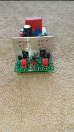
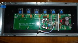
Gather 'round the campfire and let me tell you my tale of woe. I started looking into building the Wolverine around July of 2023 and by last fall I had populated the boards and completed low volt isolation testing without incident. Then life, my health and home repairs got in the way for about 6 months but I was able to continue building in earnest starting in June of '24. My build arrangement is as follows;
EF3-3 using MJL4321/4302 @71V rails. At the time
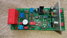
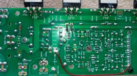
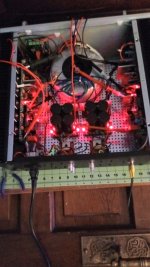
I jumped in, only EF3-3 boards were available. Drivers are the MJE15032/15033 and I used 3503E/1381E where listed on the schematic. About 2 weeks ago I completed all testing found in section 20 of the guide and over a few hours I successfully set the bias and other voltages with the trimpots and that's when my fortunes took a serious turn for the worst! As I was pulling my screwdriver away from the bias pot, I caught the tip of the tool on the front panel of the chassis knocking the screwdriver from my grasp. There was a small spark and what I think happened is the speaker output got shorted to either speaker ground or to the negative voltage rail. There is no carbon anywhere or any visible damage but all the transistors on both the IPS and the output boards were destroyed along with D1,D2. All other diodes test as functioning. Thinking the damage was limited to just the semis, I matched up another batch of transistors and replaced the damaged parts. I swapped the rail fuses back to 2A fast and hooked up the DBT for another go and here's where it got weird.... As expected the bulb flashed brightly and dimmed before it pulsed 2 or 3 times and all the LEDs went out except the +rail indicator. I shut the power off when the lamp started pulsing but the transistors did not make it. Obviously I didn't find all the shorted components so I'm hoping someone can help me ID the offending component. The rail fuse did not blow the second time and the DBT didn't save the semis! I should also mention that the speaker protection board was damaged for that channel as well.
So close...and yet so far! Let me know if you need more info or pics to help with sleuthing on this issue.
Jim
Gather 'round the campfire and let me tell you my tale of woe. I started looking into building the Wolverine around July of 2023 and by last fall I had populated the boards and completed low volt isolation testing without incident. Then life, my health and home repairs got in the way for about 6 months but I was able to continue building in earnest starting in June of '24. My build arrangement is as follows;
EF3-3 using MJL4321/4302 @71V rails. At the time
I jumped in, only EF3-3 boards were available. Drivers are the MJE15032/15033 and I used 3503E/1381E where listed on the schematic. About 2 weeks ago I completed all testing found in section 20 of the guide and over a few hours I successfully set the bias and other voltages with the trimpots and that's when my fortunes took a serious turn for the worst! As I was pulling my screwdriver away from the bias pot, I caught the tip of the tool on the front panel of the chassis knocking the screwdriver from my grasp. There was a small spark and what I think happened is the speaker output got shorted to either speaker ground or to the negative voltage rail. There is no carbon anywhere or any visible damage but all the transistors on both the IPS and the output boards were destroyed along with D1,D2. All other diodes test as functioning. Thinking the damage was limited to just the semis, I matched up another batch of transistors and replaced the damaged parts. I swapped the rail fuses back to 2A fast and hooked up the DBT for another go and here's where it got weird.... As expected the bulb flashed brightly and dimmed before it pulsed 2 or 3 times and all the LEDs went out except the +rail indicator. I shut the power off when the lamp started pulsing but the transistors did not make it. Obviously I didn't find all the shorted components so I'm hoping someone can help me ID the offending component. The rail fuse did not blow the second time and the DBT didn't save the semis! I should also mention that the speaker protection board was damaged for that channel as well.
So close...and yet so far! Let me know if you need more info or pics to help with sleuthing on this issue.
Jim
Attachments

Hi legis31,
To troubleshoot things, look at the damage and mark the parts on a schematic. Then follow were the fault current went and test those parts as well. Don't just fire it up though! You can use a bipolar variable supply. You can also use a variac carefully.
The dim bulb tester won't save things depending on the situation. As I have said a thousand times, use a variac. A decent variac has volt and ammeters on it, or you can add them.
I tried a dim bulb tester ages ago. Went right back to the variac. The dim bulb throws too many variables into the mix, and it doesn't limit the voltage, only current. When the current is higher, the voltage is lower. So you never really know exactly what voltage levels are and they frequently change - making troubleshooting more difficult. There is only one reason a dim bulb tester is popular. It's cheap.
I have never encountered an amplifier being more damage by short-circuit when the right bulp is selected for a DBT at power up. It's definitely way better then no DBT and just full AC if mistakes are present. Even the most obvious small overlooked mistakes can cause serious damage, and we do make mistakes now and then.
A variac is on my wishlist, like many other nice things for the workbench🙂
A variac is on my wishlist, like many other nice things for the workbench🙂
@anatech, How would the variac have prevented the disaster in this case?
Dropping a screwdriver into a live chassis seems like a sure fire way for some excitement! I wasn't using the DBT or the variac when I dropped the tool.
Since there's no visible damage on the boards or components and since I can only offer a guess as to what was actually shorted to what, how does one begin to try and figure out where the fault current went? My diagnostic skills are not my strong point.
As fireanimal mentioned, start with the blown components and move backwards through the circuit testing each part. You can physically just look at the boards and follow the trace, but the schematics will also be useful to mark off where you have already tested and find the next spot to check… if you can’t follow schematics easily, just methodically check each component one by one… Caveat: I’m new to this myself, but that’s what I would do at this point..how does one begin to try and figure out where the fault current went?
I appreciate the rapid response, guys. I just need to organize myself and format a methodical approach. I was hoping for a magic wand based on scant information and a single clue; the pulsating dbt when I fried the transistors the 2nd time. I've also been laboring under the assumption that since the original short was on the output board then the shorted mystery component must be on the output board as well? Hope I didn't paint myself into a corner so to speak.
Dropping a screwdriver is something that would have destroyed everything it did even if you had just turned the power off. So we aren't talking about this.
It would have prevented your second set of parts from dying. As for troubleshooting, that is a combination of logic skills and knowing how parts work. Generally, semis normally blow short. So on your schematic draw a short if it died that way. You'll soon be able to figure out where excessive current went, or high voltages. You have a trail of breadcrumbs. So mark the original damaged parts, stuff in between is suspect. Resistors can go open without burning - so measure. Never assume anything, prove it! OFten that means pulling the part.
Another thing, and this is very important. You can test for junctions (diode drops) and beta with BJTs. Transistors can go leaky or intermittent with temperature after seeing a surge. Modern leakage testers (cheap transistor testers) are simply not sensitive enough to read it unless it is really bad. Your ohmmeter probably won't either. We're talking uA, and it can cause failure. Leakage increases rapidly with temperature. You need to measure collector-base and collector-emitter. I just rejected an output transistor due to C-B leakage, it would have caused the circuit to fail later. The beta measured high.
Never assume anything.
Hi hcpower,
I have ... plenty of times.
People who use dim bulbs normally are not experienced at all, have less good test equipment and a weaker understanding of what to watch out for. I trained electronic techs for years. As I said, the one and only reason dim bulb tests are popular is because people didn't spend the money on the right tools. You can call it a cost of admission, but sorry. Some stuff you really do need. Can you wield a soldering iron without it? Yup. I see the results of this every darned day. It didn't use to be this way.
My first warranty contracts had a list of absolutely required equipment listed as a make and model. You had to use those or better. No discussion. A variac was on that list and almost every required equipment list I have seen. They were not trying to be elitist, they needed people to repair things efficiently without blowing warranty parts up or causing more damage to equipment. Not so today, service is dead and folks heading up service departments are often untrained as well. Wonderful.
I not 100% sure which protection board your asking about. But if its the speaker protection board, that was designed by Jeremy @jjs.What is the protection Pcb
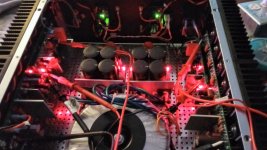
Glad that you like the photos. I was happy with what I got done today.
Hi legis31,I was hoping for a magic wand
I’m sorry to hear about the issues you’ve encountered with your Wolverine build. It can be quite frustrating when you're so close, yet obstacles keep popping up. Here’s some targeted advice that might help you identify and resolve the underlying problem:
1. Check Resistors: Inspect all resistors to ensure there are no open circuits, shorts, or unusual resistance values. Use a multimeter for precise measurements.
2. Inspect Diode PN Junctions: Use your digital multimeter (DMM) in diode mode to check all the PN junctions of the diodes. If any readings appear unusual, consider removing the component from the board to double-check its functionality.
3. Test PNP Transistors: For PNP transistors, place the negative lead on the base and check the forward voltage from the collector to the base, and the emitter to the base. Ensure there is no reverse bias by reversing your leads. Use your DMM in diode mode, and if anything appears off, remove the component to verify.
4. Test NPN Transistors: For NPN transistors, place the positive lead on the base and check the forward voltage from the base to the collector, and from the base to the emitter. Again, ensure there is no reverse bias by reversing your leads. If readings are abnormal, take the component out for further inspection.
5. Utilize a Variac: Instead of starting at full voltage, use a variac to slowly increase the voltage, starting with maximum resistance on R109. Monitor the current draw on both rails to detect any shorts or irregularities. If you manage to reach approximately 30 volts without issues, the circuit should begin to function.
6. Live Circuit Testing: If everything seems to be in order and you are not blowing fuses, but you suspect they still maybe an issue, recheck all PN junctions carefully while the circuit is live. With your DMM in voltage mode, verify that you have approximately 0.6V across each PN junction. If not, turn off the power and examine the component further.
With these steps, you should be in a good position to identify and resolve the faults. Best of luck, and I hope you can continue progressing on your Wolverine amp build!
Agreed. Wow. Very nice build.@stuartmp I've just seen your latest Google photos, looks great.

- Home
- Amplifiers
- Solid State
- DIY Class A/B Amp The "Wolverine" build thread