Hello,
A few technical questions:
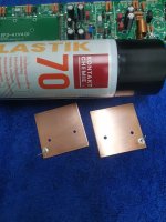
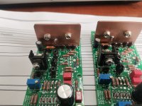
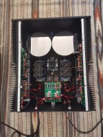
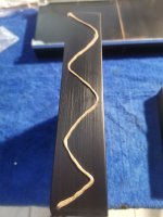
1. following one of the suggestions mentioned in this thread I created the shortcut as shown on the attached photo (it's FF3-3 ver 3.9 board). It links IPS nfb with the input of the OUTPUT coil. Is there anything else I should also do?
2. what is the optimum value for Rlift (2.2 or 4.7ohm), has anyone checked that in practice? In most of my amps I used resistors of about 5 ohms. What's the optimum value here?
3. what is the minimum value of C4 and C5 caps? With which transistors that minimum can be achieved?
4. what Q1-Q2 Hfe value was used here for calculations? I have plenty of various low noise transistors such as ss914, 2n5087, 2sa1085, 2sa970bl so I could choose one of these rather than BC560 which although low noise is less linear than the ones I mentioned.
5. what changes between the first version and the current resulted in the reduction of slew rate from 75V/us to 67v/us?
6. what is the maximum acceptable distance between IPS board and the main board?
Thanks for any comments and suggestions,
cheers,
A few technical questions:
1. following one of the suggestions mentioned in this thread I created the shortcut as shown on the attached photo (it's FF3-3 ver 3.9 board). It links IPS nfb with the input of the OUTPUT coil. Is there anything else I should also do?
2. what is the optimum value for Rlift (2.2 or 4.7ohm), has anyone checked that in practice? In most of my amps I used resistors of about 5 ohms. What's the optimum value here?
3. what is the minimum value of C4 and C5 caps? With which transistors that minimum can be achieved?
4. what Q1-Q2 Hfe value was used here for calculations? I have plenty of various low noise transistors such as ss914, 2n5087, 2sa1085, 2sa970bl so I could choose one of these rather than BC560 which although low noise is less linear than the ones I mentioned.
5. what changes between the first version and the current resulted in the reduction of slew rate from 75V/us to 67v/us?
6. what is the maximum acceptable distance between IPS board and the main board?
Thanks for any comments and suggestions,
cheers,
Attachments
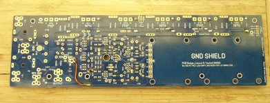
1. This is not a shortcut, It was tested to be a the lowest distortion path. It links the output trace (pre inductor) to the inverting input of the differential pair in the input stage via the feedback network. It is not the "input of the OUTPUT coil". You may want to go a bit easier with the solder and the flux or you may develop creepage issues around your transistor legs.1. following one of the suggestions mentioned in this thread I created the shortcut as shown on the attached photo (it's FF3-3 ver 3.9 board). It links IPS nfb with the input of the OUTPUT coil. Is there anything else I should also do?
2. what is the optimum value for Rlift (2.2 or 4.7ohm), has anyone checked that in practice? In most of my amps I used resistors of about 5 ohms. What's the optimum value here?
3. what is the minimum value of C4 and C5 caps? With which transistors that minimum can be achieved?
4. what Q1-Q2 Hfe value was used here for calculations? I have plenty of various low noise transistors such as ss914, 2n5087, 2sa1085, 2sa970bl so I could choose one of these rather than BC560 which although low noise is less linear than the ones I mentioned.
5. what changes between the first version and the current resulted in the reduction of slew rate from 75V/us to 67v/us?
6. what is the maximum acceptable distance between IPS board and the main board?
2. From our testing a wide range of values are acceptable with no clear optimal component so if you have 2.2 or 4.7ohm resistors use them. Basically please just refer to the BOM.
3. The table in the BOM shows the minimum values of C4 & C5 and which transistors need to be modified to run them. Once again, with our testing what we show on the BOM is the recommended minimum values. C4 & C5 among other things control the UGCF (unity gain cross over frequency) of the amplifier. It is possible, and we did test lower values for C4 & C5 which increased the UGCF but to maintain the rest of the stability tests which we developed for the sim & real life testing of the Wolverine this would have required other components to be changed and you sort of end up where you started. So there is nothing to gain by seeking lower compensation values.
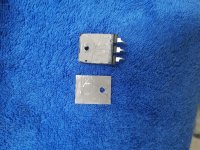
4. For Q1-Q2 I believe 559C is the recommended component. Other transistors were tested and are listed in the BOM as well. We did test a number of other transistors, and not all were included in the BOM for various reasons. Some of the other guys in the Wolverine team may have a better memory than me on this matter and may comment later on this point. There maybe other transistors that will work suitable well but the ones we show in the BOM were shown to be the most compatible across all voltages. They were also listed as highly readily available components.
For what its worth they tested very well. See attached. Some transistor trade noise for gain, so the noise figures may look really good but the gain has dropped off significantly to achieve this.
5. Nothing has changed your probably comparing different results. One with C4 & C5 at 68pF & 470pf and the other at 56pF & 300pf
6. Please refer to the BOM and build guide for guidance on the maximum acceptable distance between IPS board and the main board. It all depends on the male and female SIP headers you ordered and have installed.
Last edited:
Thanks Stuart,
I do not have BC559c so I asked. I have many BC560Cs, these are closest to BC559c. My guess would be 2sa1085 as the lowest noise choice.
What I meant was "the shortest path", which it is so one could expect it to be the lowest distortion path. I'll follow your advice and use silver solder here. I use it for soldering semiconductors. Makes a difference.
So 100pF and 470pF are the optimum values for c4 and c5, however in the building guide experimenting with lower c4-5 values is invited. I think I'll test a couple of other combinations as I will use different driver and power transistors in my EF3-3 and different in EF3-4.
Thanks for your thorough explanation, other builders will also benefit from it.
cheers,
Q1 and Q2 are not the dominant source of noise, so swapping those will not make a difference. BC560C's are my preferred for both noise and distortion, followed by BC559C and BC327-40.
I suggest you re read Stuart's paragraph 3 above before changing the value of C4 and C5. Everyone thinks they can reinvent the wheel overnight, but those values have been tested, proven, tested and proven again. If you want lower values then you need to use the 2sc/2sa series as per the BOM.
I suggest you re read Stuart's paragraph 3 above before changing the value of C4 and C5. Everyone thinks they can reinvent the wheel overnight, but those values have been tested, proven, tested and proven again. If you want lower values then you need to use the 2sc/2sa series as per the BOM.

I know noise level of Q1-2 is not that essential here but I have plenty of low noise transistors I'll never use in this life so I wondered... Anyway, following your suggestion I'll use BC560c (Fairchild not Philips) here and keep 2sa1085 for some discrete preamp i might build in the future.
Yes, in my EF3-4 (+/-64V) I'll be using 2sa1859a/sc4883a and 2sa2223a/sc6145a. In my EF3-3 (+/-71V) I'll be using MG6331/9411 but I'm hesitating which drivers to use: mje15xxx or 2sa1859a/sc4883a. This amp is to drive mid (above 400Hz) and high range speakers possibly 4 ohm. Mje15xxx are certainly safe here while 2sa/sc I think should survive as well and I like fast drivers. Anyway, I'll probably play safe and use mje15xxx.
Thanks for your comments fireanimal,
cheers,
The 2SA1859A 2SC4883A have no issues with 71V rails and would be preferred over the MJE series for the reasons I stated above.
That was my original intention to use these drivers and I mentioned that here but someone commented that EF3-3 at +/-71V with 2sa/sc drivers driving nominal 4 ohm speakers might be risky.
I have to add that my heatsink for EF3-3 is not that large: 300mm x 125mm x 35mm but above 400Hz there is no more than 50% of power and MGs will manage for sure. I'll probably reduce bias to 80-85mA to keep everything a touch cooler.
So you say 4 ohm is no problem. OK, thanks.
I have to add that my heatsink for EF3-3 is not that large: 300mm x 125mm x 35mm but above 400Hz there is no more than 50% of power and MGs will manage for sure. I'll probably reduce bias to 80-85mA to keep everything a touch cooler.
So you say 4 ohm is no problem. OK, thanks.
Yeah no issues with those, you may have been thinking of the 2SC4793 2SA1837 which are not recommended for 71V rails.
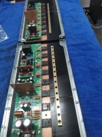
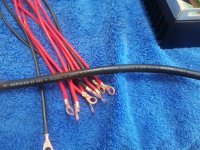
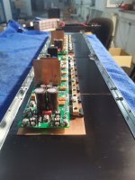
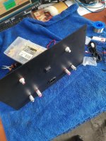
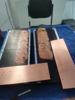
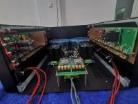
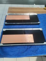
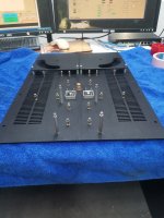
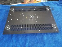
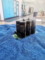
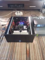
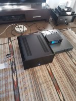
Hello all, after 2 months of work i have finished this project, it whas a lot of work. In the end it whas well worth it, verry nice sound and good performance. Thanks wolverine team.
Attachments
-
 WhatsApp Image 2023-10-15 at 03.14.16_fb03829d.jpg473.6 KB · Views: 228
 -
 WhatsApp Image 2023-10-15 at 03.14.17_e62a9b38.jpg496.6 KB · Views: 211
 -
 WhatsApp Image 2023-10-15 at 03.14.18_0efb7c3a.jpg309.7 KB · Views: 205
 -
 WhatsApp Image 2023-10-15 at 03.14.19_5b619a1e.jpg456.5 KB · Views: 204
 -
 WhatsApp Image 2023-10-15 at 03.14.18_bf4aadba.jpg668.5 KB · Views: 214
 -
 WhatsApp Image 2023-10-15 at 03.14.20_5a8ad557.jpg379.7 KB · Views: 216
 -
 WhatsApp Image 2023-10-15 at 03.14.20_927c6879.jpg311.5 KB · Views: 202
 -
 WhatsApp Image 2023-10-15 at 03.14.21_2eb28403.jpg419.8 KB · Views: 214
 -
 WhatsApp Image 2023-10-15 at 03.14.22_53e10449.jpg479.7 KB · Views: 216
 -
 WhatsApp Image 2023-10-15 at 03.14.24_0d0768ea.jpg450.1 KB · Views: 208
 -
 WhatsApp Image 2023-10-15 at 03.14.23_5ef6a544.jpg649.6 KB · Views: 206
 -
 WhatsApp Image 2023-10-15 at 03.14.24_f428108e.jpg422.7 KB · Views: 211
 -
 WhatsApp Image 2023-10-15 at 03.14.25_00b4ff28.jpg688.1 KB · Views: 211
 -
 WhatsApp Image 2023-10-15 at 03.14.25_656a37fe.jpg558.3 KB · Views: 216
 -
 WhatsApp Image 2023-10-15 at 03.14.26_6a1f7d1c.jpg443.8 KB · Views: 228
 -
 WhatsApp Image 2023-10-15 at 03.14.27_51a4a2b5.jpg463.9 KB · Views: 226
 -
 WhatsApp Image 2023-10-15 at 03.14.26_99062698.jpg430.1 KB · Views: 211
 -
 WhatsApp Image 2023-10-15 at 03.14.28_47cb0757.jpg626.8 KB · Views: 220
 -
 WhatsApp Image 2023-10-15 at 03.14.28_95d32c02.jpg244 KB · Views: 203
 -
 WhatsApp Image 2023-10-15 at 03.14.29_cfa58c16.jpg533.5 KB · Views: 220
Is #1, the not short cut, needed on the newer boards(gb2) ?1. This is not a shortcut, It was tested to be a the lowest distortion path. It links the output trace (pre inductor) to the inverting input of the differential pair in the input stage via the feedback network. It is not the "input of the OUTPUT coil". You may want to go a bit easier with the solder and the flux or you may develop creepage issues around your transistor legs.
2. From our testing a wide range of values are acceptable with no clear optimal component so if you have 2.2 or 4.7ohm resistors use them. Basically please just refer to the BOM.
3. The table in the BOM shows the minimum values of C4 & C5 and which transistors need to be modified to run them. Once again, with our testing what we show on the BOM is the recommended minimum values. C4 & C5 among other things control the UGCF (unity gain cross over frequency) of the amplifier. It is possible, and we did test lower values for C4 & C5 which increased the UGCF but to maintain the rest of the stability tests which we developed for the sim & real life testing of the Wolverine this would have required other components to be changed and you sort of end up where you started. So there is nothing to gain by seeking lower compensation values.
4. For Q1-Q2 I believe 559C is the recommended component. Other transistors were tested and are listed in the BOM as well. We did test a number of other transistors, and not all were included in the BOM for various reasons. Some of the other guys in the Wolverine team may have a better memory than me on this matter and may comment later on this point. There maybe other transistors that will work suitable well but the ones we show in the BOM were shown to be the most compatible across all voltages. They were also listed as highly readily available components.
For what its worth they tested very well. See attached. Some transistor trade noise for gain, so the noise figures may look really good but the gain has dropped off significantly to achieve this.
View attachment 1223037
5. Nothing has changed your probably comparing different results. One with C4 & C5 at 68pF & 470pf and the other at 56pF & 300pf
6. Please refer to the BOM and build guide for guidance on the maximum acceptable distance between IPS board and the main board. It all depends on the male and female SIP headers you ordered and have installed.
It's not strictly required, but if installed on the 1st or 2nd group buy boards it will improve the already low distortion results.Is #1, the not short cut, needed on the newer boards(gb2) ?
Please refer to Post #2082 for further details if you missed the post by @fireanimal
Or make sure all the other scews are loose and then try to line it up. Any time you have a number of screws or bolts holding something together it is best to start all the screws before tightening any.
Thanks.. I've got a solid core 0.8mm wire that would do perfect for the long run, so I'll stick to second option👍Within 1-2dB either way, the wire is just easier and you don't have to cut the trace
- Home
- Amplifiers
- Solid State
- DIY Class A/B Amp The "Wolverine" build thread