Any type of non linear gain can cause second harmonic distortion. It can be caused from many source but one of the most common is poorly matched transistors. I'm assuming that your taking a distortion measurement at 1Khz. If so there should be plenty of negative feedback at that frequency to bring the second harmonic down to reasonable levels even if you have a miss match. It is possible to have a bad connection somewhere in your measurement chain and this can lead to higher that expected levels. So check your wiring if this is the case. 🙂thats likely to be from poor Q1/2/3/4 match / tail resistor match
If your unsure sometimes you can inject and measure a known source of distortion to verify what your measuring.
I probably wouldn't hurt to try another one of your known good IPS boards in this output board or switch output boards to see if you can target the source of the problem. Of course checking Q1/2/3/4 your pre-drivers, drivers and outputs to match them as best you can within reasonable limits is certainly worth doing if you still trying to chase it down.
Checking R3, R4 & R7, R8 are matched to is important along with R1, R9 and R2 & R21A + R21B is worth checking too.

The 2nd sheet of the BOM should guide you well in Driver selection.Is there any advantage using the 15032/33 instead of the 15034/35 in the Wolverine?
If your trying to fine tune your selection you can look at the following points.
Things like the maximum Collector−Emitter Voltages (VCEO) have been worked out for you. So don't worry to much about that.
HFE or current gain plots.
Try and select the transistor with the flattest gain in the region in which it will operate.
Unfortunately there are no plots for fT Vs Ic or Cob graphs for the MJE15032/MJE15033 devices.
We did test successfully them along with the MJE15034/MJE15035 devices which do have fT Vs Ic plot.
In general the higher the FT frequency the better the device will preform as it will be faster. Just check the FT isn't to low at your given bias.
this can lead to instability.
In general, a lower COB is desirable because it leads to a more efficient, quicker responding transistor. A lower COB allows the transistor to switch faster. Capacitance causes a delay in the switching response due to the time it takes to charge and discharge. COB is the capacitance between the collector and base of the transistor. Having a lower COB increases the bandwidth of the transistor. which is a good thing 🙂
The Ft parameter stands for the unity-gain frequency or transition frequency. It is a key specification that indicates the maximum frequency at which the transistor can amplify signals without significant distortion. The Ft value represents the frequency at which the current gain of the transistor starts to decrease. At frequencies above Ft, the current gain decreases, leading to reduced performance. So in general the higher Ft parameter the better. If we look at the Bias current for the Drivers you will see ~15mA
Now compare the above MJE15032/MJE15033 devices to the 2SC4793. As you can see the 2SC4793 has a higher Ft frequency.
The Ft parameter indirectly impacts the phase and gain margins of the amplifier through its influence on the frequency
response of the transistors. Here is a brief video explanation if you haven't heard the terms phase and gain margins.
phase and gain margins
For a more advanced series of videos I recommend the excellent video series done by Sandro.
SWAudio Video Series
Needless to say all the devices listed in the BOM preform well so please don't hesitate to use any of the components listed.
@stuartmp, This is from post #2,638 and I perhaps wrongly wrote this transistor off.2SC4793/A1837 are "wimpy" for over 2 pair outputs.
The 2SC4793/A1837 are great for the EF3-3 and EF3-4 at 63V or less rail voltages. At higher voltages it gets to close to the SOA for comfort. A better choice for high voltage rails are the 2SC4883A 2SA1859A.
I have adjusted bias voltage to 42-44mV on a warm amp, running it for an hour or so.
Powering up on a cold amplifier, left side reached about 56mV after a minute, then slowly goes down to 42-44mV. This side have board mounted OT down.
The other side (right) has board mounted OT up, reaches about 46 but only after some minutes, then goes down to 42-44mV.
Is this normal and within tolerance?🙂
@legis31 PM me I have the drivers in large quantities. If you are in the US, postage is just a couple of first class stamps.
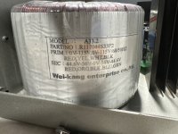
I am wondering if this transformer would be ideal for a dual mono amp.I have two of them. If you can then suggest which version of boards to use. The Primare A33.2 broken so I can reuse the case and transformers.
Attachments
Last edited:
I melted this cap a little, should I replace or might it be ok?
Since the damage is deeper then the thickness of the red cup I would replace it.
This video should give you an idea of the available clearance.
https://www.wima.de/wp-content/themes/wima/assets/img/wima-video-banner-1080.mp4
It is possible to have a bad connection somewhere in your measurement chain and this can lead to higher that expected levels. So check your wiring if this is the case. 🙂
Ah, measured again today, no 2nd harmonic 🤔 . Stuart on it as usual 😎
yes you would use the red, black, green wires on the outputI am wondering if this transformer would be ideal for a dual mono amp.
44.6 - 0 - 44.6 will give you approximately 63 - 0 - 63 volts dc rails.
The orange and blue would be to high 56 x sqrt. 2 = ~79v
Another indication of a bad connection is the width of the base of the fundamental in the FFT plot.Ah, measured again today, no 2nd harmonic
If you notice that the base of the fundamental is unusually wide where it meets the noise floor this usually indicates a bad connection in the measurement chain.
Sometimes its a simple software or driver glitch, reboot and power cycle the devices helps too
- Home
- Amplifiers
- Solid State
- DIY Class A/B Amp The "Wolverine" build thread