
The dynamic range / crest factor is not a constant. It depends on the type of music, the instruments used, the quality of the recording, and not in the last place the level of compression applied during the mastering. Furthermore, the sound level experienced while listening varies with the sensitivity of the used speakers. Imo cutting down on rail voltage is a bad idea.That's true and I appreciate your comment. Yes its something that can be quite surprising when you take a measurement.
I thought that it maybe worth checking and sharing my results.
At a listen level of 85db peeks at my seating position my peek voltage measured with my scope was about 6v
At a listen level of 95db peeks at my seating position my peek voltage measured with my scope was about 12v
At a listen level of 105db peeks at my seating position my peek voltage measured with my scope was 35.4v
105dB peeks is very loud I didn't want to listen to that for to long.
Even if you add the 8v losses and then do the maths you end up at 117w so if I have 150w I think that I'll be ok.
I'm not sure who hasn't realized that. It seems fairly straightforward, since a constant (in frequency and amplitude) repeating wave literally would have no dynamic range. "Real" music generally has dynamic range. So, I agree. Watch out for the fake music though; that'll get you all twisted up. 😉When aiming for high quality reproduction of real music (low distortion), realize that the dynamic range of real music is much higher then that of a constant repeating wave.
So do I.I like headroom.
If we're using the same definition of headroom (dB of undistorted power available above the average level)...
I usually check distortion measurements of amplifiers at various output levels into whatever load(s) I find most appropriate. You'll have to pick your own definition for "undistorted" and what type of distortion(s) matters to you.
I like about 15dB of headroom... So, If I can get roughly a 30x multiple above my average (I consider 0.5W a nice place to start for my speakers in my room) of undistorted power => 15W at a distortion level I'm comfortable with, then off we go. In this type of amplifier, I'll have more than enough headroom.
Stuart seems to take a similar approach to mine in-room also.
You're stating what many would consider to be obvious. What is your point? Recordings have dynamic range? There are numerous websites available that will show the dynamic range in a recording. Most don't go above 15dB.The dynamic range / crest factor is not a constant. It depends on the type of music, the instruments used, the quality of the recording, and not in the last place the level of compression applied during the mastering. Furthermore, the sound level experienced while listening varies with the sensitivity of the used speakers.
From what to what? Perhaps for you, and I wouldn't disagree with your decision, but overall... It should be easily measured or calculated what output voltage will deliver the SPL you seek at a distortion level to your liking and at the frequencies of concern given a typically variable load across the frequency band. My speakers are nominally 4ohm with a max impedance of ~6ohm. Therefore, I tend to choose to operate at lower rails than some others. Were my nominal impedance 8 or even 16 ohms, and/or my speakers far less efficient, my room even larger, or my seating distance even further away, then I might think otherwise. I typically cut down on rail voltage, and I think it's quite a good idea. It's not particularly relevant to this amplifier, but with Class A amplification, I find my choice to run 'lower' rails even more beneficial. One of the beauties of DIY is being able to tailor your equipment to your own desires and needs. Mine happen to differ a bit from yours. Don't get me wrong, I'm often in the 'if some is good, then more is better' camp, but it's not cut and dry that higher rails are better even within the context of more available headroom.Imo cutting down on rail voltage is a bad idea.
Long post to illustrate that running lower rails for this amp (and selecting from the myriad of wonderful devices tested by the group) will work just wonderfully for me. Maybe not everyone... but it'll be gracious plenty for me.
Cheers.
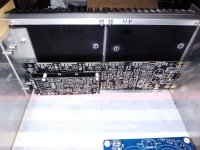
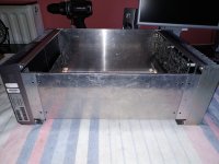
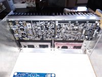
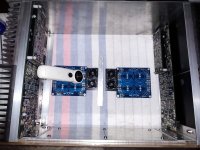
Almost finished the box....
Here I would like your opinion on the placement of the boards .
Here I would like your opinion on the placement of the boards .
Attachments
-
 IMG_20221219_125848.jpg449.1 KB · Views: 212
 -
 IMG_20221219_160041.jpg476.7 KB · Views: 206
 -
 IMG_20221219_101239.jpg594.4 KB · Views: 198
 -
 IMG_20221219_125332.jpg413.9 KB · Views: 205
 -
 IMG_20221219_125909.jpg438.1 KB · Views: 203
 -
 IMG_20221219_095805.jpg471.8 KB · Views: 213
 -
 IMG_20221219_130406.jpg466.5 KB · Views: 202
 -
 IMG_20221219_095847.jpg457.9 KB · Views: 209
 -
 IMG_20221219_160050.jpg508.9 KB · Views: 215
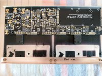
I would prefer the way in the right(101239 jpg).Has anyone mounted the boards this way so that their outputs end up on the back of the box?
Agreed, I like the outputs on the bottom third of the heatsink.
I was also thinking about how to mount the boards. I read the "how to wire an amplifier" document several times. It repeats over an over again that power wiring should be kept as short as possible. Audio input wiring should be done smart, reducing loop area, the shortest possible way is not always the best.
I think I will end up mounting both boards with their power input and speaker output section facing towards the back panel. This way power wiring and output wiring can be kept short and tidy.
As this is not a class A amp, I hope heat will not be a problem just because one of the boards is mounted with the outputs on the upper third of the heatsink.
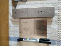
These are exactly the thoughts I have about the shortest power wiring. Of course, one board is placed in the upper third of the heatsink. My heatsink is 15.5cm tall and 27.5cm wide.I was also thinking about how to mount the boards. I read the "how to wire an amplifier" document several times. It repeats over an over again that power wiring should be kept as short as possible. Audio input wiring should be done smart, reducing loop area, the shortest possible way is not always the best.
I think I will end up mounting both boards with their power input and speaker output section facing towards the back panel. This way power wiring and output wiring can be kept short and tidy.
As this is not a class A amp, I hope heat will not be a problem just because one of the boards is mounted with the outputs on the upper third of the heatsink.
I would like more opinions if it really reaches the height of the heatsink if it is placed like this to cool properly.
The transistors that will be used are the 2sc5359 και 2sa 1987 at 64 volts
Last edited:
I believe your on the right track. It's preferable to have the AC transformer at the front of the chassis. Then have each pcb orientated so the DC power inputs are at the front of the chassis and the input signal terminals are towards the rear panel. This will mean one pcb is flipped relative to the other. Mount each pcb as low as practical to allow as much room above the output transistors as practical. Drill the two holes for the RCA inputs next to each other approximately 40mm appart on the left side of the chassis. This will keep the length of both input signal wires about the same length and minimise loop area.
It sounds like you have it under control. The how to wire an amplifier is a awesome reference.
Good luck.
It sounds like you have it under control. The how to wire an amplifier is a awesome reference.
Good luck.
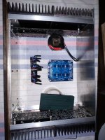
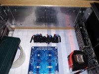
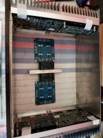
Stuart thanks for your explanation . Please look the pic and confirm the orientation of the boards ....The inputs at the back side and the power connections in the front panel near to the trafo...one board top the other at the bottom.
Attachments
Last edited:
In some of your photos it's a little hard to know which is the front and rear of your chassis but from what I can see in this photo you want to rotate each pcb 180° so the input boards are at the rear of the chassis. Feel free to move things around and send another image to confirm.
Attachments
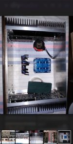
Yes that's correct and you RCA inputs will go here.Stuart thanks for your explanation . Please look the pic and confirm the orientation of the boards ....The inputs at the back side and the power connections in the front panel near to the trafo...one board top the other at the bottom.
Attachments
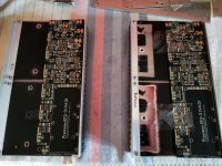
Understand......about Rca inputs and the dc power inputs placement.....but with this setup , the output transistors of the top board located at bottom third of the heatsink and the other bottom board output transistors at top third of the heatsink. Less cooler space....what do you think they will have the same behavior thermally?
Last edited:
I wouldn't be worried about that. I have seen many amplifiers were they are mounted in a simlar orientation and even closer to the upper edge.Understand......about Rca inputs and the dc power inputs placement.....but with this setup , the output transistors of the top board located at bottom third of the heatsink and the other bottom board output transistors at top third of the heatsink. Less cooler space....
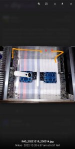
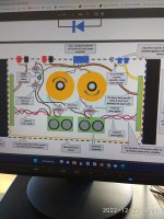
According to Bonsai.
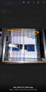
This is (blue lines)how the signal cables must be configured.
Ιn this way the power supply, transformer, rectifier, capacitors are outside the loop of the signal cables.
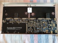
I would prefer boards placed in opposite way each other so all power transistors near the bottom side of heatshinks
This is (blue lines)how the signal cables must be configured.
Ιn this way the power supply, transformer, rectifier, capacitors are outside the loop of the signal cables.
I would prefer boards placed in opposite way each other so all power transistors near the bottom side of heatshinks
Attachments
Last edited:
I think you prefer with the placement of the boards so that the output transistors are mounted of the bottom third of the heatsink?
Regardless if one input or output is opposite giving more importance to the same thermal behavior??
Regardless if one input or output is opposite giving more importance to the same thermal behavior??
Attachments
Exactly!I think you prefer with the placement of the boards so that the output transistors are mounted of the bottom third of the heatsink?
Regardless if one input or output is opposite giving more importance to the same thermal behavior??
If you will dril simetrical you can place one heatschink easy in both ways keeping the best.
Last edited:
I think I may have answered my own question here!Hi Stuart,
Wondered if your testing of TT vs SA/SC has revealed any further insights at all to date? As it happens, not long after my last post my pcb's were delivered - I've since cracked on with my build, things have gone well so I've arrived at the stage of being able to fit these .....
Any update?
Thanks!
Of the selection of TTA/TTC's and SA/SC's I have, the TT's seem to win hands down on hfe readings ....... best TTA reads 200 vs best SA of 139, and best TTC reads 214 vs best SC of 129. SA/SC's have better Vbe readings, but as higher hfe seems to be more preferred (especially for Q101 & Q102), the TT's come out on top.
That, together with Stuarts initial findings about the TT's having less (virtually none) QSR leads me to believe these will be the better choice, for me anyway. Otherwise I might find myself ping-ponging back and fore for ages - so I'll just do it!
Onwards and upwards .....
- Home
- Amplifiers
- Solid State
- DIY Class A/B Amp The "Wolverine" build thread