I don't think I can't do this it's not possible there is no space on the heatsink and the output transistors are not the same distance from the right and left side..........I should make different holes at the same height or a little lower or a little higherExactly!
If you will dril simetrical you can place one heatschink easy in both ways keeping the best.
Last edited:
Andy should have the results tomorrow. So hopefully we will all be enlightened then. 🤞I think I may have answered my own question here!
Of the selection of TTA/TTC's and SA/SC's I have, the TT's seem to win hands down on hfe readings ....... best TTA reads 200 vs best SA of 139, and best TTC reads 214 vs best SC of 129. SA/SC's have better Vbe readings, but as higher hfe seems to be more preferred (especially for Q101 & Q102), the TT's come out on top.
That, together with Stuarts initial findings about the TT's having less (virtually none) QSR leads me to believe these will be the better choice, for me anyway. Otherwise I might find myself ping-ponging back and fore for ages - so I'll just do it!
Onwards and upwards .....

Ah, brill - I'm sure I can hang on one more day, in that case!!! 👍Andy should have the results tomorrow. So hopefully we will all be enlightened then. 🤞
According to Bonsai.
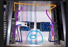
This is (blue lines)how the signal cables must be configured.
Ιn this way the power supply, transformer, rectifier, capacitors are outside the loop of the signal cables.
I would prefer boards placed in opposite way each other so all power transistors near the bottom side of heatshinks
There could be a number of ways to do this. I guess it also depends were there transformer is located. I'm currently asking @Bonsai for his advice hopefully he will have time to post. or have some time to chat with me and I'll try and update everyone as best I can.According to Bonsai.
This is (blue lines)how the signal cables must be configured.
Ιn this way the power supply, transformer, rectifier, capacitors are outside the loop of the signal cables.
I would prefer boards placed in opposite way each other so all power transistors near the bottom side of heatshinks
I uploaded two new pdf of Bonsai's to the wolverine Dropbox folder.
Thimios posted one earlier and here is the other.
Attachments

In a conventional amp layout with each module on the heat sinks either side of the case, you have a very large loop pickup area inside the amplifier that is prone to cross channel ground loops caused by the transformer mag field. The way to avoid this is not to put the connectors either side of the case, but together over to one side. Bond the signal returns together and then connect a 2 to 5 nF cap from the bonded grounds to the chassis right adjacent to them for RFI suppression. Make sure the connectors are NOT making any contact to the chassis where they are mounted - if they are, you will create a severe ground loop. Run the input cables together, dropping off at the first amp module and then run the other channel cables around the top edge to the other channel. If you instead ran the input cables directly to each module input on the assumption the shortest connection path is the best, you are in fact creating a very large loop area for transformer mag field pickup ie the worst of all worlds.
Hi BonsaiIn a conventional amp layout with each module on the heat sinks either side of the case, you have a very large loop pickup area inside the amplifier that is prone to cross channel ground loops caused by the transformer mag field. The way to avoid this is not to put the connectors either side of the case, but together over to one side. Bond the signal returns together and then connect a 2 to 5 nF cap from the bonded grounds to the chassis right adjacent to them for RFI suppression. Make sure the connectors are NOT making any contact to the chassis where they are mounted - if they are, you will create a severe ground loop. Run the input cables together, dropping off at the first amp module and then run the other channel cables around the top edge to the other channel. If you instead ran the input cables directly to each module input on the assumption the shortest connection path is the best, you are in fact creating a very large loop area for transformer mag field pickup ie the worst of all worlds.
would you like to draw on the photo the best placement of the output and input cables??
Also the placement points of the connectors.
Here is a link to a few words on this and 2 slides in a PDF doc.
https://hifisonix.com/reducing-loop-area-in-audio-power-amplifier-wiring/
🙂
https://hifisonix.com/reducing-loop-area-in-audio-power-amplifier-wiring/
🙂
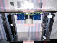
Your layout looks good Nikos because the transformer and rectifier/filter are well away from the input stages. I’ve done some photo mark ups to show how to minimize the loop area to reduce cross channel ground loops.

@Bonsai Thanks for posting these! I know these help me understand the loop area concept a lot better.
You need to check it out physically because each amps implementation is different. At least this should help you identify where you may be getting a cross channel,ground loop.
Also, always rotate the transformer by +-60 degrees to find the mag field null,point. The field is not uniform due to wire bunching and if you’re lucky you can get a noise ‘null’ of more than 10 dB. Further, make sure all power wires are tightly twisted.
Also, always rotate the transformer by +-60 degrees to find the mag field null,point. The field is not uniform due to wire bunching and if you’re lucky you can get a noise ‘null’ of more than 10 dB. Further, make sure all power wires are tightly twisted.
Your layout looks good Nikos because the transformer and rectifier/filter are well away from the input stages. I’ve done some photo mark ups to show how to minimize the loop area to reduce cross channel ground loops.
View attachment 1121489
With this example and with the diyaudio chassis having the inputs at separate sides of the rear panel would you still route both input wires the same way?
Hi @Bonsai thank you so very much for sharing your thoughts and knowledge with all of us.
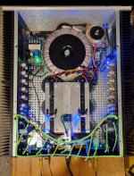
I have been reviewing what you posted and would like to know your opinion on this layout. Daniel tried it on one if his previous amplifiers a few months before he started his wolverine build and it was very successful.
I have been reviewing what you posted and would like to know your opinion on this layout. Daniel tried it on one if his previous amplifiers a few months before he started his wolverine build and it was very successful.
Attachments
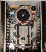
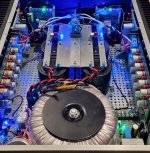
Here are a couple of photos of an amplifier I built some time ago.Hi @Bonsai thank you so very much for sharing your thoughts and knowledge with all of us.
I have been reviewing what you posted and would like to know your opinion on this layout. Daniel tried it on one if his previous amplifiers a few months before he started his wolverine build and it was very successful.
Stuart recommended @Bonsai's guide to reducing loop area.
I applied most of the suggestions in the document. Before hand it was about 300 microvolts rms on the output at idle. In the end the idle rms output voltage measured with
a 300 kHz bandwidth was 26 microvolts. with a shorted input. In other words the amplifier is "ear on tweeter quiet" at idle. In fact on a pair of large Altec horns with ~100dB 1W/1m sensitivity compression drivers you can put your ear in the horn mouth and it is silent.
I would recommend following the document.
https://hifisonix.com/reducing-loop-area-in-audio-power-amplifier-wiring/
Of course every amplifier has slightly different layout quirks and I found with that amplifier separated inputs was ok. But I used 1nF on each rca shield return to chassis.
Photos below, I hope this is helpful.
(Pretty quiet for 1.5 kVA unshielded toroid)
- Dan
Attachments
I would TRY two ways and see which is the quietest because a lot of this will depend upon the size of the transformer+rectifier+smoothing cap radiated fields.With this example and with the diyaudio chassis having the inputs at separate sides of the rear panel would you still route both input wires the same way?
1. Method 1. Run the input cable from the RCA receptacle of one of the channels across to the other and then run the cables togethe. Drop off to the first amp module and then run the cable around the top edge of the amp close to the metalwork to the other channel.
2. Method 2. Since Nikos has mounted his PSU right at the front of the case and away from the inputs, you could try direct connection to the amp modules.
Nice looking build! 👍👍For those that are interested Daniel still had a little loop area that could have been reduced further but the effort required wasn't worth it given the results he was seeing
26uV at the output on a power amp is an excellent result Daniel. I think the attention to the track routing on the PCB’s wrt minimising loop areas also plays an important role in this amps noise performance. But, it also goes to show that you have to treat the whole thing as a system to get the noise down ie PCB layout, PSU location, wire dressing and routing etc. if you neglect any one area, the noise goes up.
BTW a good test for cross channel ground loops is to cross connect the two inputs with an RCA cable. If the noise goes up, it indicates you have some mag field interference with some wiring loop in the amp.
BTW a good test for cross channel ground loops is to cross connect the two inputs with an RCA cable. If the noise goes up, it indicates you have some mag field interference with some wiring loop in the amp.
- Home
- Amplifiers
- Solid State
- DIY Class A/B Amp The "Wolverine" build thread