I have this one myselfI am considering a dc power supply. Build guide says 20-30 dc one should be fine. I presume something like this will do the job?
https://amzn.eu/d/gvDnAK0
https://www.jaycar.com.au/0-to-32vdc-dual-output-dual-tracking-laboratory-power-supply/p/MP3087

That's a sweet PS, but if bought just for testing a single build, it might be a bit to hars on the budget. Fortunate the build guide mentions a more affordable alternative. "If you do not have an adjustable bench power supply or Variac to slowly bring the voltage up, a simple current limiting incandescent lamp will work fine for initial power up."
Thanks Gareth.
Yep, I get that. Was just thinking to get something more substantial. Looks like a bulb is the way to goThat's a sweet PS, but if bought just for testing a single build, it might be a bit to hars on the budget. Fortunate the build guide mentions a more affordable alternative. "If you do not have an adjustable bench power supply or Variac to slowly bring the voltage up, a simple current limiting incandescent lamp will work fine for initial power up."
Hi Guy's
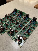
I'm just starting my EF3-4 build.
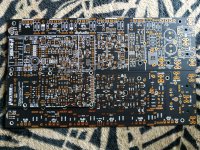
Here are some progress shots.
I've created a build album if anyone wants to follow my progress.
Wolverine Build Album
I'm just starting my EF3-4 build.
Here are some progress shots.
I've created a build album if anyone wants to follow my progress.
Wolverine Build Album
Attachments

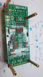

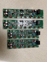
Yes, they need to be soldered as per the notes in the build guide.Questions before I start populating. These solder bridges need to be done? Why are they here?
Please choose Route 1 and solder the bridges as shown in the build guide and in my attached image.
Do not solder both route 1 & 2.
Only solder route 1.
They connect the negative feedback path to the input stage and are vitally important!
We plan to test route 2 at some stage to see if it produces lower distortion. Route 2 is slightly different to the one we tried in the first group buy.
The solder bridges gives us options.
Attachments

Last edited:
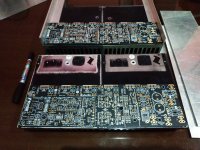
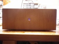
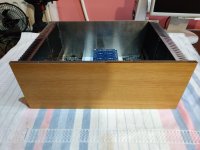
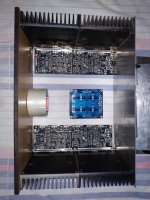
I got a job....I'll start with the construction of the box. it will be exactly the same box as in USSA 5. The boards will be placed one high and the other low so that their output is on the back side of the box. The output transistors are thus placed in this way approximately at the same height of the heatsink.the dimensions of the box will be 41cm width 27.5cm depth. and 16cm height..
Attachments


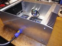
How did you cut those nice clean circular holes ?A nice thing to do on a dark winter day: cutting keratherm insulators. I realised that Keratherm is locally distributed through Conrad Elektronik in Germany. I got myself a sheet of 86/82, 190mm X 190mm in 0,25mm thickness.
The pads sold in the diyaudio store are quite big to fit for TO 247 case, but as I will use TO3-P devices I choose to cut pieces of 21mm x 27mm. That adds up to 7x9 = 63 insulators (and no waste) from my sheet. should be enough for the next few projects..
View attachment 1116558
How did you cut those nice clean circular holes ?

I used very cheap punch pliers. I had some trouble with my first tries, because the keratherm is so thin.
The solution was to put some layers of a plastic bag on both sides of the thermal pad and punch through this sandwich. That gave nearly perfect holes..

I used 72Vdc rails on mt EF3-4 build.@stuartmp ; What rail voltage are you going to be using ? I’m about to start selecting parts for a EF3-4 build and I’m probably going for 71v rails. For the BJTs I’m trying to decide, MJL3281 / 1302 or 2SC5200/2SA1943. Any reason to choose one of these over the other?
I felt that the MJL4821 MJL4302 was my best option
Hi Stuart,Indeed. Typo.. should have been saturation. I've asked the admin team to fix it 🙂
We will be testing a bunch of things to see which is the preferred transistor.
Wondered if your testing of TT vs SA/SC has revealed any further insights at all to date? As it happens, not long after my last post my pcb's were delivered - I've since cracked on with my build, things have gone well so I've arrived at the stage of being able to fit these .....
Any update?
Thanks!
I used 64v with a 800VA supply powering both rails for my Honey badger build and found that was more output power than I'm ever going to need. So for this build I'm going to build mono blocks with a 40v 500VA transformer in each. That will give me 57v rails and about 150w into 8 ohms@stuartmp ; What rail voltage are you going to be using ? I’m about to start selecting parts for a EF3-4 build and I’m probably going for 71v rails. For the BJTs I’m trying to decide, MJL3281 / 1302 or 2SC5200/2SA1943. Any reason to choose one of these over the other?
For those interested in calculating there output power I just put this little table together for you all.
Rail voltage 57v
Assume a voltage drop of 2.5v at max load.
Then;
A drop across D115 of ~0.465v
A drop across the cap multiplier of ~0.990v
A drop across the VAS current source of ~1.0v
A drop across the RCC resistor of ~0.3v
A drop across Pre driver transistors of ~0.735v
A drop across driver transistors of ~0.655v
A drop across Output transistors of ~0.735v
A drop across the emitter resistors of ~0.370v
If my math is right that's a total drop of ~7.8v
57-7.8 = 49.2V that would be equal to the voltage peek.
So the RMS would be 49.2 / Sqrt(2) = 34.78v
The Power across an 8 ohm load would then be V^2 / R = 151.3 Watts.
Please refer to sheet 2 in the bom for more information on the expected output power
Last edited:
When aiming for high quality reproduction of real music (low distortion), realize that the dynamic range of real music is much higher then that of a constant repeating wave. I like headroom.
That's true and I appreciate your comment. Yes its something that can be quite surprising when you take a measurement.When aiming for high quality reproduction of real music (low distortion), realize that the dynamic range of real music is much higher then that of a constant repeating wave. I like headroom.
I thought that it maybe worth checking and sharing my results.
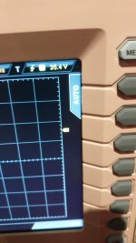
At a listen level of 85db peeks at my seating position my peek voltage measured with my scope was about 6v
At a listen level of 95db peeks at my seating position my peek voltage measured with my scope was about 12v
At a listen level of 105db peeks at my seating position my peek voltage measured with my scope was 35.4v
105dB peeks is very loud I didn't want to listen to that for to long.
Even if you add the 8v losses and then do the maths you end up at 117w so if I have 150w I think that I'll be ok.
Attachments
I'm going with the NJW0281G / NJW0302G as they have proven to be the lowest distortion.@stuartmp ; What rail voltage are you going to be using ? I’m about to start selecting parts for a EF3-4 build and I’m probably going for 71v rails. For the BJTs I’m trying to decide, MJL3281 / 1302 or 2SC5200/2SA1943. Any reason to choose one of these over the other?
But the MJL3281 / 1302 are a great choice for Higher output power setups. Having said that I'd still use the NJW0281G / NJW0302G if I was running 64v rails and 8 ohm speakers.
- Home
- Amplifiers
- Solid State
- DIY Class A/B Amp The "Wolverine" build thread