Τ
My active heatsinks fan keep rock steady the temp at 42_45 C on upper aluminium at bottom of the heatsink and at the metal body of mosfet about 55-57 C. Ambient temp summer 30 C.
Is this Luxman amp class A?
Hi OS thanks for your kind words..That one is interesting , using big CPU vapor phase change (heatpipe) heatsinks to cool the outputs.
Luxman is only OEM i've seen that in.
Nice layout on that wolverine 3-pair OPS !!
My active heatsinks fan keep rock steady the temp at 42_45 C on upper aluminium at bottom of the heatsink and at the metal body of mosfet about 55-57 C. Ambient temp summer 30 C.
Is this Luxman amp class A?
Hi ghitus thanks for your kind words.Hi @Nikos, congrats for your Wolverine, but what's the other amplifier?
Ga.
The other amp it is the Alpha Nirvana 39 version 4R class A from AKSA.
A Very detailed colourful amplifier very very pleasant.
Last edited:

Hi Nikos,
This technology is used to transfer heat from a PCB where you can't mount a normal heat sink to an area where you can, or use fans better. Better CPUs use a pumped water cooling system. The main issue is the pipe connection to the fins is a friction fit, not bonded in any way. Inefficient. Then the fins are too thin for good radiation. Check manufacturers of heat sinks for this data. The actual phase change stuff works.
I don't know of any audio manufacturer that uses this technology any more. If it worked well, they would use it for sure. If it works for you - great. I suspect a normal heat sink properly sized would work better. So it isn't wrong, I just wouldn't do it that way due to past experience. I own a pair of Luxman M-02 amps, the output stage runs hotter than it should. Often the grease has been cooked solid, no longer "greasy".
Your build is nice and clean. That I like.
All designs using this are class A-B to the best of my knowledge.Is this Luxman amp class A?
This technology is used to transfer heat from a PCB where you can't mount a normal heat sink to an area where you can, or use fans better. Better CPUs use a pumped water cooling system. The main issue is the pipe connection to the fins is a friction fit, not bonded in any way. Inefficient. Then the fins are too thin for good radiation. Check manufacturers of heat sinks for this data. The actual phase change stuff works.
I don't know of any audio manufacturer that uses this technology any more. If it worked well, they would use it for sure. If it works for you - great. I suspect a normal heat sink properly sized would work better. So it isn't wrong, I just wouldn't do it that way due to past experience. I own a pair of Luxman M-02 amps, the output stage runs hotter than it should. Often the grease has been cooked solid, no longer "greasy".
Your build is nice and clean. That I like.
Hi anatechOften the grease has been cooked solid, no longer "greasy".
Your build is nice and clean. That I like.
many thanks for the info...
So cooking.....ohhhh high temperatures.
Thanks again .
Hi Nikos,
If it works okay for you, use it. Don't change anything.
On those Luxman amps, you often have to snap the outputs off the block. The grease had become solid, I've serviced many. I'm not sure if most heat is lost off the pipe, or fins. I suspect the pipe - lol!
If it works okay for you, use it. Don't change anything.
On those Luxman amps, you often have to snap the outputs off the block. The grease had become solid, I've serviced many. I'm not sure if most heat is lost off the pipe, or fins. I suspect the pipe - lol!
I have spending many hours and models for clamping about Mosfets.
The problem was the the trapped temperature in the upper part of the mosfet and not on its metal surface which anyway is removed through a heatsink and a fan. for this an extra aluminum surface was adapted.
The problem was the the trapped temperature in the upper part of the mosfet and not on its metal surface which anyway is removed through a heatsink and a fan. for this an extra aluminum surface was adapted.
Attachments
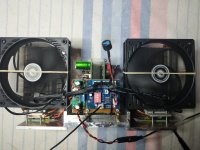
Fans aren't great anyway. You now own a vacuum cleaner in disguise!
Too much tech in the fan controller. Fan with mains powered AC motor (more expensive, but they don't fail). Series resistor for low speed operation (quiet) and a thermal switch that shorts the resistor out when the temperature is raised (party time!). Very reliable.
Best is convection cooling only. Make the conventional heat sink the proper size, you don't need a fan, and you don't need to clean it out.
Using the dual channel for initial testing of at 30VDC and .3 amps have I set the Dual supply Tekpower up correctly, running it in series?For this amp you will always need symmetrical rail power. Positive_Zero_Negative.
So if you want to test at a rail voltage of lets say +30V 0 -30V, one dual_channel bench power supply (capable of delivering the needed voltage and current) will do. If the bench power supply is only single channel you will need two.
And to run at full voltage (+60V 0 -60V) using single channel 0-30V bench power supply's, you need four.
It's like loading a flashlight, for 6V light bulb you need four 1,5V batteries
Attachments
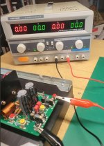
That supply is two seperate supplies. If there is a tracking switch, turn it on. Actually, set this one to "series", the centre two switches. Then the following:
You need to connect the neg term of one to the positive of the next. That is your common "ground". Your positive is positive, negative from the negative.
I would connect the neg of the left supply to the positive of the right. That is what they intended.
You need to connect the neg term of one to the positive of the next. That is your common "ground". Your positive is positive, negative from the negative.
I would connect the neg of the left supply to the positive of the right. That is what they intended.
Using the dual channel for initial testing of at 30VDC and .3 amps have I set the Dual supply Tekpower up correctly, running it in series?
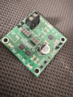
I don't have Photoshop at hand on this PC, hope the draft drawing is sufficient. Notice the markings at the PCB terminals too.
With this wiring, setting the supply at independent should work.
Usually it also works in series mode, but I have no experience with this particular model.
Parallel will not work.
Notice ground on the PSU is not necessary the same same as ground on amp, here it's not.
Check everything with DMM before connecting.
Thanks guys. I will digest this and come back to make sure I get it right. The manual is of very little use, at least to me, so your help goes a long way.
Please check the video I made on the subject.Using the dual channel for initial testing of at 30VDC and .3 amps have I set the Dual supply Tekpower up correctly, running it in series?
Dual supply
Guys... for that particular PSU... RTFM. The connections for running it in series ARE NOT intuitive (to me). The manual provides specific instructions (specifically for current limiting). The connections I'd intuitively make are not what the manual says. The manual is the source of truth.
One of you has provided instructions to a new user that I believe will make their PSU and/or their amp go POOF. Now, I admit that I could have it completely wrong, since I am a novice also, but... I'd recommend referencing the manual and the "Master / Slave" relationship of the supplies vs. left and right etc. when operated in series using the buttons vs. just leaving the supplies operating independently.

Edited to add - I'll leave this up... but I was exercising an over-abundance of caution. I missed one key, key word from above... pasted below to give credit. "With this wiring, setting the supply at independent should work.". Sorry for the false alarm. I admit I was trying to look after another user and got too far over my skis. I learn too.
One of you has provided instructions to a new user that I believe will make their PSU and/or their amp go POOF. Now, I admit that I could have it completely wrong, since I am a novice also, but... I'd recommend referencing the manual and the "Master / Slave" relationship of the supplies vs. left and right etc. when operated in series using the buttons vs. just leaving the supplies operating independently.
^ THAT!Read the manual.
Edited to add - I'll leave this up... but I was exercising an over-abundance of caution. I missed one key, key word from above... pasted below to give credit. "With this wiring, setting the supply at independent should work.". Sorry for the false alarm. I admit I was trying to look after another user and got too far over my skis. I learn too.
Last edited:
Setting for "independent" would make it so you have to adjust both voltage adjust controls. Normally a series connection makes the slave supply track the main. If I had to guess, the left side would be the main supply, the right the slave.
Current limiting would save the supply, to try it reduce the current limit to 50 mA, don't connect anything and adjust the left supply and watch the meters. Higher limits should also prevent damage, a lower current limit just keeps temperatures down.
Nothing wrong with being very cautious, especially if this stuff is new to you.
This is the biggest take away.Check everything with DMM before connecting.
The following may help you as well.
Before connecting your power supply unit (PSU) to your amplifier boards, it is crucial to verify the output voltage from your PSU using a Digital Multimeter (DMM). For added accuracy and safety, use two DMMs if possible. Ensure that your PSU is providing a dual voltage supply of +V / 0V / -V. In this instance, you should measure +30V, 0V, and -30V, where 0V is the common ground reference.
1. Setup DMM for Measurement:
- Turn on your DMM and set it to measure DC voltage.
2. Measuring the Positive Voltage (+30V):
- Connect the positive (red) probe to the +V output of the PSU.
- Connect the negative (black) probe to the 0V ground of the PSU.
- Confirm that the DMM reads +30V. This verifies the positive rail of your dual voltage supply.
3. Measuring the Negative Voltage (-30V):
- Connect the positive (red) probe to the 0V ground of the PSU.
- Connect the negative (black) probe to the -V output of the PSU.
- Confirm that the DMM reads -30V. This verifies the negative rail of your dual voltage supply.
4. Understanding the Ground (0V) Reference:
- The negative input of your DMM is typically used as a reference point. Since the DMM is a fully floating device, it measures voltage differences between probes. Therefore, all voltages are referenced to the point where you connect the black probe.
By checking both the positive and negative voltages as described above, you ensure that the PSU outputs the correct voltages, which is crucial before connecting to your amplifier boards to prevent potential damage.
While nonsense is written faster then it can be corrected the gain of any contribution becomes negative. Remind me if I forget.Guys... for that particular PSU... RTFM. The connections for running it in series ARE NOT intuitive (to me). The manual provides specific instructions (specifically for current limiting). The connections I'd intuitively make are not what the manual says. The manual is the source of truth.
One of you has provided instructions to a new user that I believe will make their PSU and/or their amp go POOF. Now, I admit that I could have it completely wrong, since I am a novice also, but... I'd recommend referencing the manual and the "Master / Slave" relationship of the supplies vs. left and right etc. when operated in series using the buttons vs. just leaving the supplies operating independently.
^ THAT!
Edited to add - I'll leave this up... but I was exercising an over-abundance of caution. I missed one key, key word from above... pasted below to give credit. "With this wiring, setting the supply at independent should work.". Sorry for the false alarm. I admit I was trying to look after another user and got too far over my skis. I learn too.
^ I don't disagree. I admit that I saw the photo with the "series" configuration buttons pressed and your proposed wiring, and I reacted too quickly without noticing your careful addition of "independent" in the text.
If it's better to remove the posts and following conversation after, I'm totally fine with that. I have no issues with admitting / owning an error. Cheers.
If it's better to remove the posts and following conversation after, I'm totally fine with that. I have no issues with admitting / owning an error. Cheers.
- Home
- Amplifiers
- Solid State
- DIY Class A/B Amp The "Wolverine" build thread