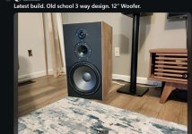
Nice clean build Stuart.
I'd love to try a stereo pair on the Klipsch Jubilee. Right now running off a pair of Bryston 4B cubed. I wish they were mine!
I'd love to try a stereo pair on the Klipsch Jubilee. Right now running off a pair of Bryston 4B cubed. I wish they were mine!
I have little polks. Polk is "mid". Careful , those monoblock Wolverines could kill those speakers.Polk RTi A7
I have the drivers , 10" 250W woofers ... 5" ferrofluid mid , dome tweeters. DIY speakers for my DIY amp.

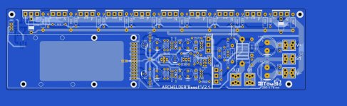
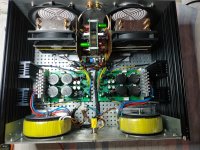
very nice 😍 ST hey you don't mind if I show this on my YouTube channel this is certainly a nice motivation 😊 I still on this design trying to improve my PCB layout design skills and is also a nice mental exercise too 😁Finally finished one of the Wolverine monoblocks. Now just the wiring to go on the second.
Attachments

Sure go ahead. Please post a link here to your video once it's done.very nice 😍 ST hey you don't mind if I show this on my YouTube channel this is certainly a nice motivation 😊 I still on this design trying to improve my PCB layout design skills and is also a nice mental exercise too 😁
You would still have to be careful , you need something like ferrofluid cooled "party speakers". Acoustic suspension 500W woofer....I'd love to try a stereo pair on the Klipsch Jubilee
Wolverine begs for 75mm voice coil - 8KG magnet monsters.
OS
Attachments
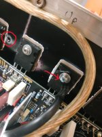
Your design would have current loop area issues. The original design with the IPS/VAS where it is makes for the PPM performance.I still on this design trying to improve my PCB layout design skills
As well as the P/N/P/N (everything cancels). For a non modular board , just integrate whatever input stage - permanent (in the blank spot).
Attachments
Hi guys,
I noticed In the Build Guide photos (Section 12 page 29 of Build Guide dated 7-10-23 Revision 41) that what look like insulating washers are used underneath nuts that are securing the pcb's to stand-offs. Is it a requirement to insulate the boards in this way or can stainless steel washers be used?
Many thanks,,
John
Hi John,insulating washers
Yeah, they were just there to stop the board being scratched by the stand offs and nuts during the populating of the boards.
Last edited:
Ok, thanks Stuart. I now have all the components for the build except for the transformers.
John
John
sorry Pete by mistake I use the report I wrote a positive comment and I forgot to "Quote" 🤣 yes I agree but it does look cool right? 😄Your design would have current loop area issues. The original design with the IPS/VAS where it is makes for the PPM performance.
As well as the P/N/P/N (everything cancels). For a non modular board , just integrate whatever input stage - permanent (in the blank spot).
It would work (the "pretty" PCB), but remember the tests that showed even the slight routing change of NFB killed the THD.
A long power loop would do even worse. I IS pretty , Vargas !
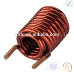
I 'm curious why the Wolverine output inductor is not the cancelling type. What I mean is one wound layer with a outer wound layer
in reverse. Full cancellation of EMF. My little Sonance 260 amp actually has this , even as they did not take NFB from the center of the EF2.
(I fixed that).
OS
A long power loop would do even worse. I IS pretty , Vargas !
I 'm curious why the Wolverine output inductor is not the cancelling type. What I mean is one wound layer with a outer wound layer
in reverse. Full cancellation of EMF. My little Sonance 260 amp actually has this , even as they did not take NFB from the center of the EF2.
(I fixed that).
OS
Attachments
oh I will then incorporate that way coil up L1 and yes I agree is "pretty on my eyes" but might have some issues I aware of that yes I'm also worried about THD too can you post a photo or link to take a look at My little Sonance 260 amp? I mean if you can 😊
Go to the Sonance 260 thread - https://www.diyaudio.com/community/threads/sonance-sonamp-260.337552/page-2#post-7787200My little Sonance 260 amp
I reverse engineered it. Up or sideways don't matter if the coil is self cancelling. Most OEM's don't have coils like this , just ones that are
designed for loads (under 3R).
Hello my friends.
Since after finishing my last amplifier Alpha Nirvana 39/4R with great success in terms of the result in sound quality.
I decided to deal with the small problem I had in my amplifier Wolverine 3ΕF at 57-59V here and two years since I believed that the smaller heatsinks with dimensions 27cm x 16cm x 5 cm I had were my issue and as many times I mentioned it, I didn't have any technical instructions.....(small complaint) ..
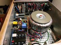
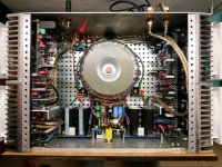
However, it wasn't the relatively small heatsinks that were wrong...I changed the position of the transistor from the heatsink to one of the output transistors....Νοw the bias reaches 45-47mv at 38 C degrees in the heatsink and when it reaches 40-45 C it decreases and stays at 40-41mv......
This is for the friends who have a similar topic.
Ηowever, it is a very strong neutral amplifier which, when warmed up, performs qualitatively better.....
Since after finishing my last amplifier Alpha Nirvana 39/4R with great success in terms of the result in sound quality.
However, it wasn't the relatively small heatsinks that were wrong...I changed the position of the transistor from the heatsink to one of the output transistors....Νοw the bias reaches 45-47mv at 38 C degrees in the heatsink and when it reaches 40-45 C it decreases and stays at 40-41mv......
This is for the friends who have a similar topic.
Ηowever, it is a very strong neutral amplifier which, when warmed up, performs qualitatively better.....
Attachments
Last edited:
That one is interesting , using big CPU vapor phase change (heatpipe) heatsinks to cool the outputs.Since after finishing my last amplifier Alpha Nirvana 39/4R with great success in terms of the result in sound quality.
Luxman is only OEM i've seen that in.
Nice layout on that wolverine 3-pair OPS !!
OS
Attachments
Hi OS,
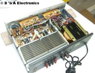
Marantz and a few others used vapour phase heat sinks. The Lux M-02 is one example. The odd service guy blew products up since "standard service position" was the unit on it's side. Those heat sinks must be level to work properly.
I don't like these heatsinks. In practice, the fin to pipe connection is poor, and the fins are not thick enough to be effective. They were less expensive and lighter than standard heat sinks. These were abandoned later. I think another reason they were used was to make slim case as was the style in the early 1980's.
- Home
- Amplifiers
- Solid State
- DIY Class A/B Amp The "Wolverine" build thread