Where is R133? I cannot find it anywhere, neither on schematics nor in parts list.Hi @mainframe99
Thanks very much for your reply. I'd figured the asterisk was probably just because the R133, R112 and R113 were higher wattage resistors, and had soldered them with an appropriate gap under them. I have done this for all the resistors >1/4W. There are quite a number more than those 3 though, and they don't have an asterisk on the PCB and that's what confused me. Thought I may be missing something.
I have watched all Daniels videos multiple times, but there are still some conflicts I haven't resolved. Thanks anyway though.
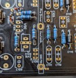
Hi @janusz it's only on the EF3-4 board I think. Above the inductor coil is J104, R133, R112 and R133. The Dale resistor in my photo of my part-built board. The EF3-3 has 133A and 133B inWhere is R133? I cannot find it anywhere, neither on schematics nor in parts list

 stead on the BOM
Hi Folks,
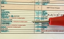
I need help with the note on the B.O.M. for R127A and R127B. I have the EF-3-4 (V4.0) boards. The note indicates these resistors are only used for 3 output pairs. I'm using 4 output pairs. The place for those resistors is clearly marked next to Q116. If you are using 4 outputs pairs, do you install these resistors?
Many thanks,
John
The BOM lists different values for EF3-3 and EF3-4 for these components. The build guide lists the EF3-4 ones as #127A/B and the EF3-3 as *127A and *127B indicating those values are only for the EF3-3 boards. In the BOM they are listed as “R126AB to R127AB” as the components in these locations have the same values. At least that’s my understanding…The place for those resistors is clearly marked next to Q116. If you are using 4 outputs pairs, do you install these resistors?
Attachments
Last edited:
Thanks Stepping3D! 127A/B is 127A and 127B. The values are different depending upon how many pairs of output transistors you are running. Thanks again.
Has anyone used the 2SA1216/2SC2922 Sankens for Wolverine?
I searched the thread, but came up empty with my search even though they are one of the two MT200 Sankens on the tested list. I'm curious how these perform compared to the 2SA1295/2SC3264 as they look very similar spec wise.
I searched the thread, but came up empty with my search even though they are one of the two MT200 Sankens on the tested list. I'm curious how these perform compared to the 2SA1295/2SC3264 as they look very similar spec wise.
2SA1295/2SC3264 is what I will be using in mine. Already got mine ordered from the forum member RM. He can match and is good dude to work with.
I haven’t seen anyone use them and talking to Andy about them they should perform well. I have 90% of the parts for my wolverine so I guess I’m going to get started on this build!
I haven’t seen anyone use them and talking to Andy about them they should perform well. I have 90% of the parts for my wolverine so I guess I’m going to get started on this build!
Last edited:
Thank you, now I know where R133 is on your board. You must have a new version of E3-4 board. Mine is v3.9 and it has R127 where you have R133. Judging by the resistor numbers new EF3-4 board versions must have a few resistors added.Hi @janusz it's only on the EF3-4 board I think. Above the inductor coil is J104, R133, R112 and R133. The Dale resistor in my photo of my part-built board. The EF3-3 has 133A and 133B inView attachment 1350811View attachment 1350812stead on the BOM
Hi all, I have a query re EF3-4 (V4.2) board. Next to the GND PIN of the predriver heatsink is what looks like a solder bridge, and I can't figure whether it needs filling or not, or even if it matters? It seems to only connect to the GND PIN of the driver heatsink and that isn't being mounted anyway on this board.
Attachments
Hi all,
I'm getting organized to test my right channel boards for the first time. The guide recommends using a dual rail power supply. A friend has at least two DC regulated supplies and I have seen this photo with two of them connected up from Stuart's photos [attached]. But the photo doesn't show the ground connection. I have searched the forum but I'm looking for a guide for setting up two DC power supplies correctly. I'd appreciate someone pointing me in the right direction. Also, an explanation of why the need for two supplies.
Thanks
Attachments
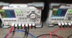
What you see on that picture are two bench power supply's each capable of 2 X 0-30V nominal and 1 X 5V. The 0-30V outputs are all set to max, and are all connected in series, for a total output 4 x 32V = 128V. Half way it's taped (the black wire), so it can be used as a 2 x 64V PSU. Positive output is on the far left and negative output is on the far right (not visible on the picture). Safety earth is not connected and that's common in this situation.
With mentioned settings, it's NOT adjusted for testing with reduced voltage!
With mentioned settings, it's NOT adjusted for testing with reduced voltage!
For this amp you will always need symmetrical rail power. Positive_Zero_Negative.
So if you want to test at a rail voltage of lets say +30V 0 -30V, one dual_channel bench power supply (capable of delivering the needed voltage and current) will do. If the bench power supply is only single channel you will need two.
And to run at full voltage (+60V 0 -60V) using single channel 0-30V bench power supply's, you need four.
It's like loading a flashlight, for 6V light bulb you need four 1,5V batteries
Thank you, now I know where R133 is on your board. You must have a new version of E3-4 board. Mine is v3.9 and it has R127 where you have R133. Judging by the resistor numbers new EF3-4 board versions must have a few resistors added.
Thanks Stepping3D! 127A/B is 127A and 127B. The values are different depending upon how many pairs of output transistors you are running. Thanks again.
The BOM lists different values for EF3-3 and EF3-4 for these components. The build guide lists the EF3-4 ones as #127A/B and the EF3-3 as *127A and *127B indicating those values are only for the EF3-3 boards. In the BOM they are listed as “R126AB to R127AB” as the components in these locations have the same values. At least that’s my understanding…
Hi Guy's
Please check the revisions listed at the bottom of the BOM.
Some ID were updated to provide further clarity.
Please also ensure you are using the correct BOM for the boards that you have to avoid further confusion.
Yes this jumper only needs to be soldered if you are installing the driver heatsink on the board.Hi all, I have a query re EF3-4 (V4.2) board. Next to the GND PIN of the predriver heatsink is what looks like a solder bridge, and I can't figure whether it needs filling or not, or even if it matters? It seems to only connect to the GND PIN of the driver heatsink and that isn't being mounted anyway on this board.
Whatever you decide to do you must always verify the voltages are symmetrical using a DMM before you connect anything to the boardsDo I just use one regulated DC supply for the reduced voltage testing
Finally finished the speaker protection boards tonight. It’s all slowly coming together. Thanks to @felix1024 for the boards and pre programmed ATtiny84. Next step… finish the rest of the soldering on the Wolverine output stage… 🙂

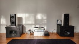
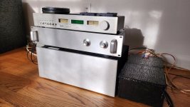
As my renter moved out, upper rooms empty, I set up second wolverine (available for sale, local pick up only) with signal selector with jlh buffered volume and nice speakers (peerless with hiquphon tweeter) on two subs. Passive parasound crossover. Magnum Dynalab just for looks. To keep it silver. Sounds clean with amazing authority. No eq, no measurements done. Room is too lively, great for choral music.
Attachments
- Home
- Amplifiers
- Solid State
- DIY Class A/B Amp The "Wolverine" build thread