
When you slow, you blow. And it looks like the well has run dry for the ZTX550 (bipolar PNP 45V 1A ) for the balanced LXmini crossover I bought from the Linkwitz Store. Or maybe just on my side of the pond here in Germany? DigiKey is telling me 34 weeks. Mouser says November 28. Just about all the other sources are for the trade only. Anyone know of a source that deals with Europe? Or, is there a substitute?
When you slow, you blow. And it looks like the well has run dry for the ZTX550 (bipolar PNP 45V 1A ) for the balanced LXmini crossover I bought from the Linkwitz Store. Or maybe just on my side of the pond here in Germany? DigiKey is telling me 34 weeks. Mouser says November 28. Just about all the other sources are for the trade only. Anyone know of a source that deals with Europe? Or, is there a substitute?
use BC556
pinout, take care
it'll work, no sound difference
What would be the max input voltage (signal) with no attenuation at the input if a 30V (max) PSU is used?
euro21,
I can see you know your way around, and this Yankee is one happy benefactor.😛 Thank you so much! And to boot, the price is fantastic!
Thanks a million Zen Mod. As you can see, euro21 found them for me, but I'll put your tip in my files for future reference. All The Best.use BC556
pinout, take care
it'll work, no sound difference
matter of principle
check prices for BC556 at TME
its role in most Papa's designs is universal bipolar transistor - so any decent one will do the job
it just happens that I'm buying BC in hundreds ........... while you can be sure that Pa bought (each time) at least thousands
on his side of Big Pond - ZTX
on my side of Big Pond - BC
if you insist on being punctual, for ZTX450/550 look for BC 639/640
So I take one of the J113 and its hand-picked bias resistor, and I put it in a circuit and measure a current between, to me, two unknown points with an unknown amount of voltage. Then if I am lucky I have a value of the current in milliampere. Then I try to replicate the same value with my unobtainium 2SK170, and burn as many jfets as I need to find the right resistor.The bias is determined by the current source, the J113 with the appropriate Source resistor. The Idss of the 2sk170 is incidental. Conventionally the current would want to be at this figure or lower.
I think I should stick to the J113.
Okay, at least I should be able to find out the pinouts and Idss . But I don't even know if I need Idss.

Last edited:
Hello rewind,
you have to adjust the bias - resistor of your CCS (the lower JFets in each buffer cell of the 6-24-XO) to run your active device (upper JFet in the schematic) to your desired 'sweet spot'.
Whatever your 'sweet spot' is - lowest possible distortion - or the sweetest sounding balance of H2/H3-
distortion?
I would use the J113 for the CCS and the LSK170 or 2SK170 as the active device in the buffer cell.
If you have bought the 2SK170 already, then you should know in which mA-range they should run.
Now you measure your J113 and adjust the bias-resistor of the J113 to get the desired mA-value
running through your active upper JFet.
There is some measuring and matching-work waiting for you!
Have fun! Enjoy the sound!
Cheers
Dirk 😉
Hello rewind,
two articles of Mr. Pass to understand better how to drive a JFet...
https://www.firstwatt.com/pdf/art_h2.pdf
https://www.firstwatt.com/pdf/art_sweet_spot.pdf
Cheers
Dirk
two articles of Mr. Pass to understand better how to drive a JFet...
https://www.firstwatt.com/pdf/art_h2.pdf
https://www.firstwatt.com/pdf/art_sweet_spot.pdf
Cheers
Dirk
I thought the bias resistors for the J113 that I got in the package was just set and forget. Not something I should tune to my liking. But nice to have that as an option in the future.Hello rewind,
you have to adjust the bias - resistor of your CCS (the lower JFets in each buffer cell of the 6-24-XO) to run your active device (upper JFet in the schematic) to your desired 'sweet spot'.
Whatever your 'sweet spot' is - lowest possible distortion - or the sweetest sounding balance of H2/H3-
distortion?
I would use the J113 for the CCS and the LSK170 or 2SK170 as the active device in the buffer cell.
If you have bought the 2SK170 already, then you should know in which mA-range they should run.
Now you measure your J113 and adjust the bias-resistor of the J113 to get the desired mA-value
running through your active upper JFet.
There is some measuring and matching-work waiting for you!
Have fun! Enjoy the sound!
Cheers
Dirk 😉
I know how to measure the Idss individually on both the J113 and lsk170/2sk170, and I will check them all using the method from DIYaudio in the image above.
The active JFETs thst is recomenned to upgrade are both Q1 and Q2 in this photo?
My problem is I don’t know how to adjust the bias resistors to get the desired mA-value. Nor where to measure, and using what power source, and in which curcuit.
Hello rewind,
if you build your 6-24XO with the J113s delivered in the kit, then you can solder them in (at the correct spots!)
and use the selected bias resistors from the kit - you are done.
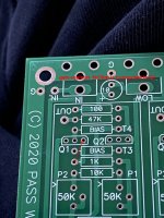
On the pic of the pcb you can see, that the 1kOhm - resistor is connected to the gate of Q1. So Q1 is the
active device in the signalpath. Q2 is the CCS. Check schematic.
if you build your 6-24XO with the J113s delivered in the kit, then you can solder them in (at the correct spots!)
and use the selected bias resistors from the kit - you are done.
On the pic of the pcb you can see, that the 1kOhm - resistor is connected to the gate of Q1. So Q1 is the
active device in the signalpath. Q2 is the CCS. Check schematic.
Attachments
If you want to tune a JFET to a resistor, you need to make a copy of the circuit and power it, and find the resistor/JFET combo that hits the right current. But if you have the kit you are as said good to go.I thought the bias resistors for the J113 that I got in the package was just set and forget. Not something I should tune to my liking. But nice to have that as an option in the future.
I know how to measure the Idss individually on both the J113 and lsk170/2sk170, and I will check them all using the method from DIYaudio in the image above.
The active JFETs thst is recomenned to upgrade are both Q1 and Q2 in this photo?View attachment 1080274
My problem is I don’t know how to adjust the bias resistors to get the desired mA-value. Nor where to measure, and using what power source, and in which curcuit.
Thanks, I do have the kit. It would just be nice to be able to upgrade Q1 to 2SK170, since I have it. But if there is no simple way for a novice, then I may give up on upgrading and just use the J113.If you want to tune a JFET to a resistor, you need to make a copy of the circuit and power it, and find the resistor/JFET combo that hits the right current. But if you have the kit you are as said good to go.
Q2 is just a constant current source and the bias is set by the Source resistor to ground. The Source resistor of Q1 is not actually necessary and you can replace it with a short. If you want to replace Q1 with a 2sk170, then you can do that and leave Q2 as a J113, but set it's bias resistor so that Q2 runs approximately at the Idss of Q1 or a bit less. Remember that 2sk170 has a different pinout.
Okay, less parts, sounds good.Q2 is just a constant current source and the bias is set by the Source resistor to ground. The Source resistor of Q1 is not actually necessary and you can replace it with a short. If you want to replace Q1 with a 2sk170, then you can do that and leave Q2 as a J113, but set it's bias resistor so that Q2 runs approximately at the Idss of Q1 or a bit less. Remember that 2sk170 has a different pinout.
Then I wonder where to measure the current I am getting. I assume it needs to be measured while the 2SK170 Q1 and J113 Q2 JFETs are mounted on the 6-24 crossover PCB board.
Then I can try random values of resistor that are close enough to the old bias resistors without anything blowing up. Unless there is a formula to calculate the bias resistors on Q2.
I hope it is nothing as complicated as this: https://www.theengineeringknowledge.com/jfet-biasing-method/
I will continue reading the linked articles after work.
Hello rewind,
you measure your current running through your JFet over the bias resistor.
Ohms law: U/R = I
Cheers
Dirk
you measure your current running through your JFet over the bias resistor.
Ohms law: U/R = I
Cheers
Dirk
Can the green 10uF Muse caps be replaced with something like a really good 1uf film cap? A really good 10uf film cap is too expensive, especially times eight.
In the guitar amp world small caps like the 0.047uf and 0.022uf that I am planning to use for 210Hz@LR24 gets a lot of attention. Orange caps are popular, like the 6PS (fast and chunky type of sound), Sozo caps (nicer than Mallory), and Mallory. Poly caps like the Wima FPK in the BOM, and Xicon styrene caps gets a bad rep, and to some extent Mallory for being too dark and harsh.
The speed of the cap is highly sought after, I guess how fast it charges and discharges. Vintage caps can sound slower, from what I read.
Last edited:
- Home
- Amplifiers
- Pass Labs
- DIY biamp 6-24 crossover