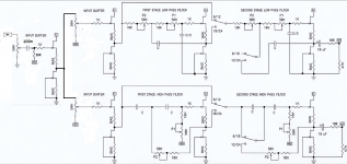
To avoid confusion: the circuit within the yellow marker is the BIAMP 6-24 Crossoverboard from the diyaudio shop.

you don't need Rsource with upper ones, just with lower ones (CCS)
counting that you have cap after each cell, no need of chasing some special DC level (output being on same level as input gate)
edit: I don't know circuit if you don't post schm or link to
counting that you have cap after each cell, no need of chasing some special DC level (output being on same level as input gate)
edit: I don't know circuit if you don't post schm or link to
I added a resistor to CCSyou don't need Rsource with upper ones, just with lower ones (CCS)
I dont understand what you mean, sorry.counting that you have cap after each cell, no need of chasing some special DC level (output being on same level as input gate)
edit: I don't know circuit if you don't post schm or link to
Here the original circuit, I want to add a additional front end and when needed modify the shown input.
@zm: I try to clear up our confusion. I am sorry!

The yellow part is the unchanged original circuit, wich is topic from this thread.
The left part is "my new" front end, for volume control and buffered.
Will this work?
@Nelson Pass: can you confirm please? No cap needed between the new frontend and the first buffer stage?
Thanks ZM and Nelson!
The yellow part is the unchanged original circuit, wich is topic from this thread.
The left part is "my new" front end, for volume control and buffered.
Will this work?
@Nelson Pass: can you confirm please? No cap needed between the new frontend and the first buffer stage?
Thanks ZM and Nelson!
Addition: please look at post #1002, then you will understand what I am looking for.
Attachments

if arranged as that, you must keep source resistors in upper portion of buffer
observe, you'll see that buffer is practically biased ( Iq set) with source resistor in lower JFet ( CCS), while role of upper source resistor is to establish so-so same DC levels at buffer input ( upper JFet gate) and its output
yeah - if having matched JFets in range of 9mA, just keep all source resistors of same value
whatever you have in range of 4R7 to 10R
I just matched the FETS for the new frontend. All other FETS are J113 I got together with the print. I did not measure the IDSS. They all use 100R BIAS resistors.
Should I also use 100R in this case for the new front end?
Should I also use 100R in this case for the new front end?

One more question: in my hobbybox, I found two J109 7mA IDSS double p-channel JFETS. Could I use it for a B1 buffer by just changing Source and Gate?

no, more complicated - needing proper flip of everything - sources going up, drains being down, best using GND and negative rail
save them for something in future, more critical and of benefit having proper ( scarce ) P channel duals
save them for something in future, more critical and of benefit having proper ( scarce ) P channel duals
Hello Franz Gysi,
I would think about using them in a BA-1-frontend. Or any other circuit which is worth those precious
TOSHIBA J109s.
Cheers
Dirk
I would think about using them in a BA-1-frontend. Or any other circuit which is worth those precious
TOSHIBA J109s.
Cheers
Dirk


Ha ha ha... I left fake bag out for ZM.
Is potato fets.

Is potato fets.
- Home
- Amplifiers
- Pass Labs
- DIY biamp 6-24 crossover