I have the Minidsp 4x10HD, but I am hoping ot build this and get rid of some noise.
Long signal chain? Tilt my curve?
The speaker level is just to divide the midrange horns from the Raal ribbon at 2000 Hz, also with an autotransformer to pad the midrange horn with -8dB. The speaker level crossover at 2000 Hz is doing something right, not sure what exactly, but I would prefer having just a cap on each driver for security.
I have a pair of 15" Beyma coaxial built into large tannoy style cabinets. Considering this as a project so that the current tube amp (2.6W) driving everything could be relegated to mid/tweeter only and something beefier can move the 15" pro driver...
Just need to decide on what to drive the woofer with but I'm glad to have stumbled across this while browsing the diyaudiostore 😀
Just need to decide on what to drive the woofer with but I'm glad to have stumbled across this while browsing the diyaudiostore 😀
Question about the kit
Hi Everyone,
I've bought the kit from the diyaudio store, and it looks great.
A quick question about it. I searched this thread as well as I could but couldn't find an answer, so probably it's obvious to everyone but me. In his article Nelson says:
"In the kit from diyAudio the Jfets used are selected for Idss and matched for performance. Each is paired with a resistor (labeled BIAS) specific to that Fet for optimal performance." (My emphasis.)
This sounds like each of my 24 jfets has been matched with an individual resistor, but in my kit I have 25 resistors in a bag marked BIAS, and another bag full of jfets, but no indication of which resistor goes with which jfet. So I presume this means it doesn't matter which resistor goes with which jfet, perhaps because the resistors all measure so close. I haven't measured idss on the jfets, although it wouldn't be hard if necessary.
So does it make any difference? Did I miss something? I thought I should ask before soldering 24 jfets and then having to take them all off again. Wouldn't be the first time I've made a dumb mistake because I didn't ask...
Best
Nigel
On the schematic, the input capacitors are shown as .1 mfd, but on the board they are labeled "10", in the same fashion as the output caps, which I assume means 10 mfd. What values are folks using for input and output?
So does it make any difference? Did I miss something? I thought I should ask before soldering 24 jfets and then having to take them all off again. Wouldn't be the first time I've made a dumb mistake because I didn't ask...
I have so many of the Jfets that I can easily come up with 24 matched
to one resistor value. Makes my life easier.


Thanks for the clarification. I wondered if it would be something like that. Now I'm certain, I can get soldering!
Best
Nigel
Best
Nigel
Need a little help
Hi All,
This is my first post after about 10 years of enjoying the diy forums. I just received the 6-24 board and find that i need a little help.
I have built a pair of 845 amplifiers (ASL AQ 1006) that i have been using for almost 20 years now. So i know how to follow a schematic and solder...my problem is that i struggle to understand the circuits.Further, i have been a open baffle/full range driver guy, so for a long time i have studiously avoided the whole crossover issue.
What brings me here now is that i heard a friend’s horn setup and felt i had to try to build a horn system. i bought a pair of Yamaha 6681b compression drivers and horns to use with my full range drivers (Audio Nirvana 15’s) now in transmission line cabinets employed for the frequencies below 600hz.
I’ve done a complete 180 and find myself lost in unknown territory.
I’ve got to say that i am very pleased with the horns. I contacted Martin Seddon of Azurahorn in Australia and bought a pair of 350 Le Cleac’h horns. I’ve never met Martin in person, but i have corresponded with him quite a bit and he is a fantastic guy and one of the nicest people i have come across in audio.
The Azurahorns are beautifully made and reasonably priced and Martin was kind enough to provide a custom made 600hz 1st order crossover to get me started. I cannot recommend him highly enough.
It is the best sound i have ever had in my home, but you fellow fanatics know how it is....and then there’s COVID and the prospect of being inside all winter in NH...
So i thought to take on this active crossover and an amplifier project so that i can bi-amp. So there it is - 10 years worth of writing in one post....
Here’s where i need the help....
I’ve read Nelson’s paper on this crossover a few times and every post in this thread. I am struggling trying to use the info i’ve read together with the calculator tool that has been so kindly provided.
I started out with the 1st order at 600hz just as in Nelson’s paper.
To do this, is it correct that i just have to populate the 1st stage after the buffers and set the jumpers to 6/12 and set R1 to 1meg and c5 to .000001nf so that they are “open”?
The C value is 10nf = 6000/60. C/2 is 5nf
Through trial and error i come up with resistor values of 42k
The way I create an electrically flat response is to invert phase of the high pass speakers. I haven’t been able to do it another way.
How does one create a 2nd order slope?
For 18/24 db i presume that i should restore normal values to R1 and C5 and set the jumpers accordingly. However, so far when i do that i have not been able to get a flat electrical response.
My hope is to someday try to get a flat acoustical response but i am dismayed that i am having a struggle to even use the tools to create a flat electrical response.
Are there any cause/effect rules regarding changing resistor values that one can use other than trial and error? This is especially important as the number of variables increases in the higher order cases.
Sorry if my questions are off the wall. Appreciate any and all hints and guidance.
Best,
Lou
Attachments
Measuring the crossover question
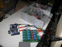
So I built one board to experiment with, but did not have a speaker that could be bi-amped easily. So I used some Jamo drivers sourced over ten years ago. Cobbled up a baffle for a test cabinet I had of about 0.58 cu ft. Two screws in the woofer, tweeter just press-fit and the port snugged up with masking tape. The baffle is just held to the box with wood clamps.
The XO was built with 3.3nF caps for 2121Hz @ 12dB. Two ACA's for power and a Peter Millet Nu-tube preamp for control.
The sound is wonderful.This just confuses me to no end. 3D soundstage and the speaker boxes seem to disappear.
How can this be? It just took a few adjustments to get what seems like a balanced set up. So what measurements can help me understand what is really happening and allow me to fine tune the crossover to the speakers?
I have a umik mike and REW. What sort of test would help me understand what is the crossover point and show phase relationships. Will simply measuring the speaker responses give me the information needed to repeat this with other drivers and or other crossover points.
Thank you in advance.
Attachments
I started out with the 1st order at 600hz just as in Nelson’s paper.
To do this, is it correct that i just have to populate the 1st stage after the buffers and set the jumpers to 6/12 and set R1 to 1meg and c5 to .000001nf so that they are “open”?
Let's start with this one.
When you set the jumpers for "6" you bypass the stage immediately
following the buffers, and you are only dealing with the next stage.
On the high pass, there are two capacitors labeled C, and the one on
the right is the one for 6 dB operation. P1 is the resistive adjustment
that goes with it. The other elements are bypassed and don't matter.
On the low pass, for 6 dB/oct C/2 is active and both P1 and P2 are in
series, so they both adjust the frequency. C is out of the circuit.
For any standard arrangement of filters, you use the C values that
are given in the formulas for the given slopes.
For 18/24 db i presume that i should restore normal values to R1 and C5 and set the jumpers accordingly. However, so far when i do that i have not been able to get a flat electrical response.
And then this one:
There are examples in the documentation for 18 and 24 db/oct slopes.
The 24 db is pretty easy, the 18 requires a little fiddling.
The examples should work. Since you can measure these, I suggest
you start there and see if you can duplicate those results. If not
we would want to look for what the problem might be.
In all cases we remember that flat electrical is typically not the best
result, rather we are usually looking for flat acoustical.
The sound is wonderful.This just confuses me to no end. 3D soundstage and the speaker boxes seem to disappear.
How can this be? It just took a few adjustments to get what seems like a balanced set up. So what measurements can help me understand what is really happening and allow me to fine tune the crossover to the speakers?
I have a umik mike and REW. What sort of test would help me understand what is the crossover point and show phase relationships. Will simply measuring the speaker responses give me the information needed to repeat this with other drivers and or other crossover points.
Lucky boy. Most of the time it takes a lot of effort to get that effect,
and success is not guaranteed.
I suggest you measure the frequency response on axis and take a
look at that. If it's flat, I would call it a day and enjoy the speakers.
Thank you Nelson
Indeed I have felt lucky with this outcome and I am cautious that too much fiddling about will move me away from this state of grace. I have three more boards and more speakers to build. Just looking for some stepping stones through the woods of self doubt to this state I have stumbled upon.
Thanks again for these great designs that sometimes seem like magic to me.🙂
Thanks for your replies Nelson! I think I am beginning to understand now. I’ll start with the basic 1st order filter and see how I do.
Thanks again,
Lou
Thanks again,
Lou
Quick update om 6-24db crossover explorations:
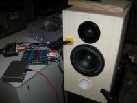
Faital 15pr400 15 inch woofers arrived last Monday. I slabbed them on a piece of leftover kitchen cabinet and put the horn on top as a test setup. Besides some noise in both the F6 and Pass ACA which these efficient drivers now reveal, the setup sounds quite alright!
I think the crossover region (x'ed at 500 hz 24db)is not too bad for my first try..😉
I really love the sounds the horn produces. Open baffle woofers not so much yet, at least not in this small, really small room.
Frequency response down low looks alright, but my ears tell me there is still some output missing.
Next steps are building enclosures for the woofer and ultimately figuring out what is the quasi optimal crossover for both smooth phase and time alignment taking into account the driver offset of 20 to 30 cm.
Maybe 24db with polarity reversed to account for driver offset?...
Maybe 24db with polarity reversed to account for driver offset?...
Only if you are very lucky. The chose of XO frequency will let you “move” the horn a bit.
dave
Exactly , the lower I get, the bigger the offset, as I got from another thread, correct?
"
4th order L-R Low Pass, -6dB @ Fx (+)
4th order L-R High Pass, -6dB @ Fx (-)
Offset = 0.31*c/Fx
"
"
4th order L-R Low Pass, -6dB @ Fx (+)
4th order L-R High Pass, -6dB @ Fx (-)
Offset = 0.31*c/Fx
"
Thanks Dave, that makes it understandable🙂 how does one find the driver offset? By measuring the distance or by looking at the phase response, or both? Ie. How accurate must this offset be, speaking in inches/mm?
- Home
- Amplifiers
- Pass Labs
- DIY biamp 6-24 crossover