True balanced vrs not. Choose your compromised.
If i needed to fake it i would just try to do it passively 1st (ie a balanced to SE cable).
dave
If i needed to fake it i would just try to do it passively 1st (ie a balanced to SE cable).
dave
Sorry, I posted the wrong reference. The article I was referring to is:
https://audioxpress.com/files/attachment/2685
It is figure 4 on page two. Simply adding a resistor to ground to match the output impedance of the positive signal.
A stupid question, but I'm still shaky on a lot of fundamentals.
If you just flip your inputs & outputs in the transformer design outlined in this article, then you've got a balanced to single ended converter, right?
I have a new dac coming that has better performance on the balanced output and a single ended dht pre-amp and have been considering building my own XLR to RCA cable with a transformer converter in the middle...
(And I have two leftover 1:1 cinemag CMOQ-4HPC transformers from a sissySIT build that look like decent candidates)
True balanced vrs not. Choose your compromised.
dave
You are talking about balanced vs. differential. I recommend reading this document:
https://www.jensen-transformers.com/wp-content/uploads/2014/08/an003.pdf
Personally, I would add as little circuitry as possible.
A stupid question, but I'm still shaky on a lot of fundamentals.
If you just flip your inputs & outputs in the transformer design outlined in this article, then you've got a balanced to single ended converter, right?
I have a new dac coming that has better performance on the balanced output and a single ended dht pre-amp and have been considering building my own XLR to RCA cable with a transformer converter in the middle...
(And I have two leftover 1:1 cinemag CMOQ-4HPC transformers from a sissySIT build that look like decent candidates)
Sure, since you have the transformers why don’t you try it.
What is better about the balanced output?
Thanks. It's a Holo Audio May. A balanced design and apparently measurements get slightly worse from the SE outputs.
At least according to:
httpss://www.superbestaudiofriends.org/index.php?threads/kte-may-technical-measurements.8933/
Stereophile stated they found no differences aside from the obvious gain decrease. I do run an F4 though, so I'm happy to take a little extra gain too.
At least according to:
httpss://www.superbestaudiofriends.org/index.php?threads/kte-may-technical-measurements.8933/
Stereophile stated they found no differences aside from the obvious gain decrease. I do run an F4 though, so I'm happy to take a little extra gain too.
I will be using my 6-24 with a tube preamp with an output capacitor. Do I need the input capacitor for the crossover?
There is adding a balanced in or out connectors to a single-ended circuit (either passively or active), but for truly balanced you use twice as many boards, 1 set for the plus phase, 1 for the negative phase.
dave
You can do this, but you will not get the CMRR benefits I believe. That will not happen before the “end” e.g. at the power amplifier’s diff input.
You are talking about balanced vs. differential. I recommend reading this document:
https://www.jensen-transformers.com/wp-content/uploads/2014/08/an003.pdf
Personally, I would add as little circuitry as possible.
Good reading. A problem with a balanced input is the added electronics, or the added transformer, even though in fact I happen to like like the transformer based approach.
It is a question, do you really need balanced in a domestic environment?
I might well do with all EMI coming from switch mode PSUs in PCs etc, and cell phones and so on. Remember though, that in a domestic environment you have short signal cables, and you are rather free to locate things in an optimal way.
/RK
Agree, but maybe I am confused. Almost all high end audiophile components use balanced connections (in addition to single ended). And almost all of this equipment are being used in domestic environment. Maybe there is a plausible reason? I am not sure.Good reading. A problem with a balanced input is the added electronics, or the added transformer, even though in fact I happen to like like the transformer based approach.
It is a question, do you really need balanced in a domestic environment?
I might well do with all EMI coming from switch mode PSUs in PCs etc, and cell phones and so on. Remember though, that in a domestic environment you have short signal cables, and you are rather free to locate things in an optimal way.
there are two most important conditions for use of fully balanced system:
1. entire signal chain must be balanced and only then you'll have all benefits and full nature of approach; that includes sources ( or main source), and it really must be proper balanced gadget, not one which is inherently SE with just glued on patch circuit to have negative phase too; example - if DA in your digital gadget is fully differential in function, then it can be logical to pursuit approach down the chain
2. that you really prefer nature of sound which Balanced is giving by nature - suppressed even harmonics in THD spectra, dominant odd ones
major benefits with balanced in pro usage are possibility to use long lines (think intrinsic suppression of common mode garbage) and , do not forget, sturdiness of interconnections - meaning both on sturdy cables and connectors
if we exclude that as major goals, no benefits in domestic usage
Agree, but maybe I am confused. Almost all high end audiophile components use balanced connections (in addition to single ended). And almost all of this equipment are being used in domestic environment. Maybe there is a plausible reason? I am not sure.
Marketing
2. that you really prefer nature of sound which Balanced is giving by nature - suppressed even harmonics in THD spectra, dominant odd ones
Thanks ZM. I think this is really important. I've just recently started learning enough to start to understand this and figure out that my ears prefer 2nd harmonic dominant. Good to see you post it just to reinforce all that learning.
And it makes me wonder if I'll end up liking the balanced dac I just purchased based on this fact (still have 2nd dominant pre-amp & amp).
This thread is drifting into the no-man's land of cable BS.
Please get back on topic.
Sorry for contributing to drift PP.
(And though this is not the place to discuss it, I'll note that one can learn about the importance of 2nd vs 3rd harmonic dominance directly from Nelson Pass... http://www.firstwatt.com/pdf/art_ba_3.pdf, The Pass H2 Harmonic Generator)
Most if not all hifi manufacturers don’t understand what a correctly balanced input stage looks like or how it works.
Ie A simple single stage opamp with +- differential inputs is highly intolerant of even small mis matches in input impedance resulting in fall off of the CMRR. Single stage balanced input stages are also relatively noisy by comparison.
Refer to Doug Self Small Signal Audio amplifier publication.
Ie A simple single stage opamp with +- differential inputs is highly intolerant of even small mis matches in input impedance resulting in fall off of the CMRR. Single stage balanced input stages are also relatively noisy by comparison.
Refer to Doug Self Small Signal Audio amplifier publication.
6-24XO experience - part2
Hello, out there!
Yes, I did it again! 🙄
My second 6-24XO build. This time for use between main speakers and subwoofer (crossover frequency around 80 - 100 Hz).
I will also try to to make the two sub-channels bridgeable to 'mono' with an
output-transformer. I have an EDCOR XS1100 (quadfilar). We will see.... 😕
I like this active crossover!
Greets
Dirk
Attachments
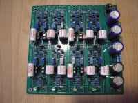
![AXO6-24_2nd_stuffed_board_closeup].jpg](/community/data/attachments/818/818520-a2871275a4fdb2e097a49f9849588c64.jpg?hash=oocSdaT9su)
24 db for ESl-2905 and SB-2000
It took some time to "finish before adjustment", but now the crossover is playing. It has been conceived to cross between Quad ESl-2905 and SVS SB-2000 subwoofers, two of both.
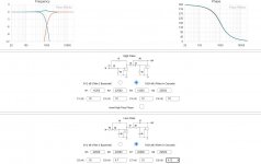
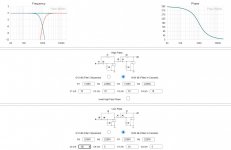
Michael (Rothacher) has provided this wonderful XO calculator for us to use. Standard is 1 kHz crossover with values of 5 nF and 10 nF for the capacitors, and 11250 and 22500 Ohms for the resistors. By scaling the capacitors to 50 nF and 100 nF respectively, one get 100 Hz crossover. I purchased 47 nF instead of 50 nF, and the summed frequency response shown in the calculator is not flat anymore. I wanted 80 Hz so I adjusted the resistances, and then some to some degree flatten the response somewhat. Shown in an attachment. (I will probably change from 47 nF to 50 nF in the future to get it "correct".) I subtracted 10 kOhms from the numbers and wrote down. I did first a course adjusment of the trimmers, turned the PCB and measured for the correct value (minus 10k) and then fine tuned the values to approximately what I wanted (what I calculated).
The next step will be to adjust the level of the bass system relative the electrostatics. The subwoofers are located somewhat behind the Quads, however the Quads simulate å point source located some 12 inches behind the diaphragm so I guess it is good enough for rock'n'roll (and all other genres as well).
To the rest of the implementation.
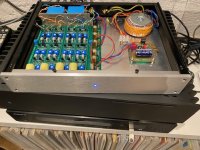
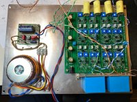
I used a 30VA 2x12V transformer Nuvotem Talema 0030P1-2-012 (RS Components 2237822) and the Velleman K1823 kit power supply (LM317). I changed the rectifiers to soft recovery types. It might deserve some capacitive multiplier between the K1823 and the filter PCB. I have real estate for a more advanced regulator.
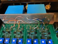
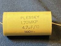
I decided I wanted film coupling capacitors, so I dug out some 10 uF ERO and some 4.7 uF Plesseys. 4.7 at the inputs and 10 uF on the outputs. Wire with zero distortion wires from CAT6 cabling. . The 10 uF blocks are placed on a experimental PCB with brackets found in an old collection of things.
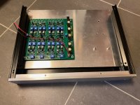
The enclosure is from eBay - large enough and nice enough. I located all the PCBs, transformers etc on an internal aluminum plate to avoid drilling in the bottom plate. (Except for the four feet.)
It took some time to "finish before adjustment", but now the crossover is playing. It has been conceived to cross between Quad ESl-2905 and SVS SB-2000 subwoofers, two of both.
Michael (Rothacher) has provided this wonderful XO calculator for us to use. Standard is 1 kHz crossover with values of 5 nF and 10 nF for the capacitors, and 11250 and 22500 Ohms for the resistors. By scaling the capacitors to 50 nF and 100 nF respectively, one get 100 Hz crossover. I purchased 47 nF instead of 50 nF, and the summed frequency response shown in the calculator is not flat anymore. I wanted 80 Hz so I adjusted the resistances, and then some to some degree flatten the response somewhat. Shown in an attachment. (I will probably change from 47 nF to 50 nF in the future to get it "correct".) I subtracted 10 kOhms from the numbers and wrote down. I did first a course adjusment of the trimmers, turned the PCB and measured for the correct value (minus 10k) and then fine tuned the values to approximately what I wanted (what I calculated).
The next step will be to adjust the level of the bass system relative the electrostatics. The subwoofers are located somewhat behind the Quads, however the Quads simulate å point source located some 12 inches behind the diaphragm so I guess it is good enough for rock'n'roll (and all other genres as well).
To the rest of the implementation.
I used a 30VA 2x12V transformer Nuvotem Talema 0030P1-2-012 (RS Components 2237822) and the Velleman K1823 kit power supply (LM317). I changed the rectifiers to soft recovery types. It might deserve some capacitive multiplier between the K1823 and the filter PCB. I have real estate for a more advanced regulator.
I decided I wanted film coupling capacitors, so I dug out some 10 uF ERO and some 4.7 uF Plesseys. 4.7 at the inputs and 10 uF on the outputs. Wire with zero distortion wires from CAT6 cabling.
. The 10 uF blocks are placed on a experimental PCB with brackets found in an old collection of things.The enclosure is from eBay - large enough and nice enough. I located all the PCBs, transformers etc on an internal aluminum plate to avoid drilling in the bottom plate. (Except for the four feet.)
Attachments
-
 IMG_3971.jpg153.4 KB · Views: 699
 -
 adjusted.JPG86.6 KB · Views: 286
 -
 4.7.JPG87.2 KB · Views: 286
 -
 standard.JPG87.8 KB · Views: 288
 -
 IMG_3972.jpg57.3 KB · Views: 339
 -
 IMG_3903.jpg163.5 KB · Views: 319
 -
 IMG_3878.jpg132.1 KB · Views: 259
 -
 IMG_3843.jpg60 KB · Views: 563
 -
 IMG_3875.jpg100.4 KB · Views: 614
24 db for ESL-2905 and SB-2000 part 2
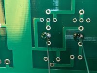
A few more pictures. Showing soldering etc.
A few more pictures. Showing soldering etc.
Attachments

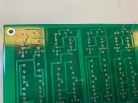

24 db for ESl-2905 and SB-2000 part 3
Pictures.
Pictures.
Attachments


Last edited:
Nice work! The XO calculator shows the electrical response of the crossover. Have you measured the acoustic response of the speakers with your crossover?
Thank you.
No, no measurements so far. That will probably not happen before 2021.
BTW the bump from using 47 nF instead of 50 nF would not have been large and maybe totally swamped by the non-linearity of the speakers and the room also. Also, 47 is within +/-10% of 50.
No, no measurements so far. That will probably not happen before 2021.
BTW the bump from using 47 nF instead of 50 nF would not have been large and maybe totally swamped by the non-linearity of the speakers and the room also. Also, 47 is within +/-10% of 50.
Last edited:
- Home
- Amplifiers
- Pass Labs
- DIY biamp 6-24 crossover