I would have started with something like 1.5 nF and 3 nF capacitors. And the 11k250 and 22k5 resistors from Michael’s XO Calc. Keeping the 5 nF and 10 nF capacitors you will need to lower the resistors to below 10k. (I might also like to check with Linkwitz-Riley Filter Calculator, 2-Way, 4th Order)
Feel free to correct me here if you think I’m wrong. For the ‘basic’ crossover at 4 poles and 2500hz all we need is 7000/2500. This gives you C of 3nf and C/2 of 1.5nf. The rest of the crossover remains ‘stock’. Micheal’s calculator is for more advanced designs?
Regards,
Dan
 Sorry for confusing people. I forgot the “7000/f rule”, still, we both proposed 2.5 and 3.
 I made two boards for 12dB only. On the first one used 3.3nf only (6000/3.3 = 1818hz) and for the second board 1.5nf (6000/1.5 = 4000Hz) . If I turn the pots up (higher resistance) the crossover point goes down and conversely if they are turned down the crossover goes up. Easy peasey to adjust. More so than I could have imagined before it was hooked up and working. Nelson did all the hard work in the design and he has given it to us to play with. Wonderful
Hello 6-24XO builders,
in my first build of the 6-24XO I also divided at 2500 Hz with a slope of
24dB/oct.
My values were the following - and it is proven to work great.
I lowered the 10 kOhm resitsors to 4.7kOhm.
But there are many ways to do it. 😉
Greets
Dirk
in my first build of the 6-24XO I also divided at 2500 Hz with a slope of
24dB/oct.
My values were the following - and it is proven to work great.
I lowered the 10 kOhm resitsors to 4.7kOhm.
But there are many ways to do it. 😉
Greets
Dirk
Attachments

Hello 6-24XO builders,
in my first build of the 6-24XO I also divided at 2500 Hz with a slope of
24dB/oct.
My values were the following - and it is proven to work great.
I lowered the 10 kOhm resitsors to 4.7kOhm.
But there are many ways to do it. 😉
Greets
Dirk
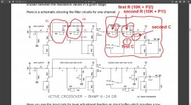
Are you referring to this part of the 6-24 PDF?
If you are dedicated to the 24 dB/oct L-R alignment, you can extend your frequency
adjustment range on this filter if you replace the high pass P2 50K pots + 10 Kohm resistor
with 25K in series with 4.7K resistors.
Regards,
Dan 🙂
to Dan
Hello Dan,
yes, I refer to that passage of Nelson Pass 6-24XO - article. Although I kept the 50 kOhm trimpots. I only lowered the resistors.
And I played around a lot with Michael Rothachers simulation. 🙄
Greets
from Dirk 😉
Hello Dan,
yes, I refer to that passage of Nelson Pass 6-24XO - article. Although I kept the 50 kOhm trimpots. I only lowered the resistors.
And I played around a lot with Michael Rothachers simulation. 🙄
Greets
from Dirk 😉
I'm intrigued because your right at the crossover frequency I'm focusing on.
I'd like to take my line arrays from passive to active and their current crossovers are both fourth order at 2500Hz.
Regards,
Dan 🙂
I'd like to take my line arrays from passive to active and their current crossovers are both fourth order at 2500Hz.
Regards,
Dan 🙂
Last edited by a moderator:
Balanced operation
Dear all
I am very new here and I am looking for a solution to create an active 2 ways crossover that operates in balanced mode.
Would that mean that 2 boards (kits) could be used for that task?
Any wiring directions?
Thanks
Christophe
Dear all
I am very new here and I am looking for a solution to create an active 2 ways crossover that operates in balanced mode.
Would that mean that 2 boards (kits) could be used for that task?
Any wiring directions?
Thanks
Christophe
If you go back abit there is a discussion of just this.
You can use double the boards to crete true balanced or a circuit or transformer can be added to the input or the output (ie balanced to SE)
dave
You can use double the boards to crete true balanced or a circuit or transformer can be added to the input or the output (ie balanced to SE)
dave
Balanced operation
Dear all
I am very new here and I am looking for a solution to create an active 2 ways crossover that operates in balanced mode.
Would that mean that 2 boards (kits) could be used for that task?
Any wiring directions?
Thanks
Christophe
Dear all
I am very new here and I am looking for a solution to create an active 2 ways crossover that operates in balanced mode.
Would that mean that 2 boards (kits) could be used for that task?
Any wiring directions?
Thanks
Christophe
to chris 64
Hello Chris64,
Start reading from post #526 in this thread. There is some information about going balanced with the 6-24XO by converting the signal from balanced to single- ended and vice versa.
If you want to go balanced (without changing the signal) you need two 6-24XO.
Your balanced signal consists of a positive and a negative signal (and ground).
You send your positive signal through the low pass and high pass filter and
negative signal through another lowpass amd high pass filter (with the same values in C and R for positive and negative signal.
So one complete 6-24XO-board for one channel balanced / two way crossover.
You should read through this thread.
I hope this helps😉
Greeets
Dirk
to Chris64
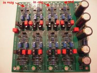
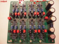
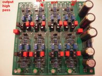
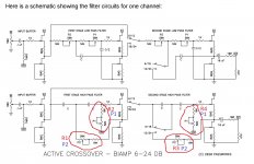
It could look like on the pics.
Your adjustments at the pots should be very exact from positive 'channel' to negative 'channel'.
Greets
Dirk
It could look like on the pics.
Your adjustments at the pots should be very exact from positive 'channel' to negative 'channel'.
Greets
Dirk
Attachments
Pa gave us more than enough practical tips, so someone should make true balanced xover with same practicality, based on this one
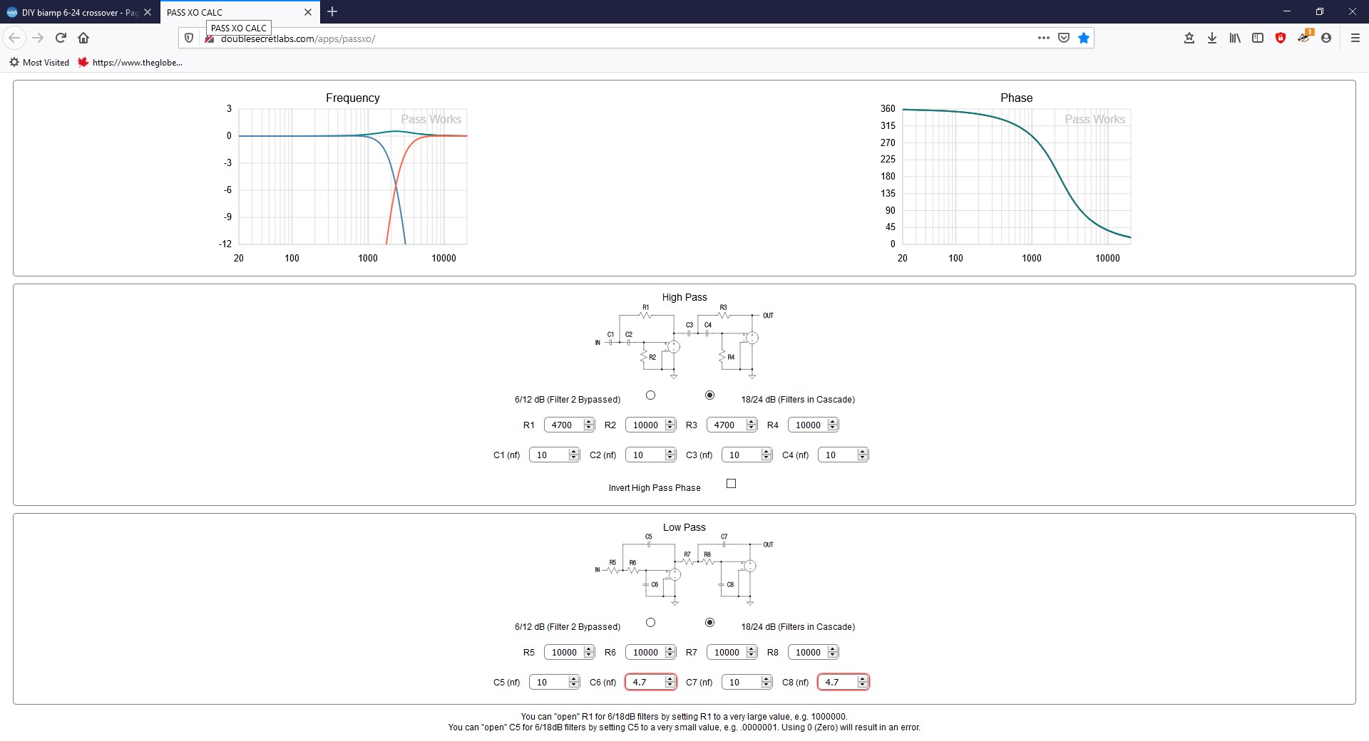
Till now I only played with the values in the simulator of Michael Rothacher.
I am focused on a 24dB crossover characteristic (steep slope).
I compared the schematic in the article of Nelson Pass with the schematic in
the Simulator of M. Rothacher.
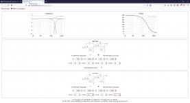
I attach some screenshots.
You can play with the values of the C's in the simulator.
I am not 100% sure which values I wanna use yet (the C's).
I changed the values of the resistors (original 10kOhm) to 4.7kOhm (in the low pass filter) and from 10kOhm in the high pass filter from 10kOhm to 6.8kOhm. Because they are always in line with the pots.Still enough adjustment range with the 50kOhm-pots.
Please be patient with me.😉 I will report back as soon as I have a result for me.
All is only simulated yet. Listening tests have to proof the simulations.
Also pay attention if you play in the simulator what your phase-shift is doing.
Greets
Dirk
This was the perfect post for me because I was still a little fuzzy on relating Pa's schematic to Michael's crossover software.
Regards,
Dan 🙂
Thanks for the capacitor value suggestions for my 3kHz X-over (3nF and 1.5nF). Can someone advise what I should be looking for in the phase characteristic on the simulator? I'm probably looking at either 6dB or 12dB / Octave settings. The tweeters are currently wired out of phase, although that is obviously easily changed if necessary. When I'm tweaking the values, I seem to get 2 or 3 separate curves on the phase graph...I assume you want the high and low pass to be at the same phase around the x-over frequency?
Jonathan
Jonathan
Till now I only played with the values in the simulator of Michael Rothacher.
I am focused on a 24dB crossover characteristic (steep slope).
I compared the schematic in the article of Nelson Pass with the schematic in
the Simulator of M. Rothacher.
I attach some screenshots.
You can play with the values of the C's in the simulator.
I am not 100% sure which values I wanna use yet (the C's).
I changed the values of the resistors (original 10kOhm) to 4.7kOhm (in the low pass filter) and from 10kOhm in the high pass filter from 10kOhm to 6.8kOhm. Because they are always in line with the pots.Still enough adjustment range with the 50kOhm-pots.
Please be patient with me.😉 I will report back as soon as I have a result for me.
All is only simulated yet. Listening tests have to proof the simulations.
Also pay attention if you play in the simulator what your phase-shift is doing.
Greets
Dirk
Hello Chris64,
Start reading from post #526 in this thread. There is some information about going balanced with the 6-24XO by converting the signal from balanced to single- ended and vice versa.
If you want to go balanced (without changing the signal) you need two 6-24XO.
Your balanced signal consists of a positive and a negative signal (and ground).
You send your positive signal through the low pass and high pass filter and
negative signal through another lowpass amd high pass filter (with the same values in C and R for positive and negative signal.
So one complete 6-24XO-board for one channel balanced / two way crossover.
You should read through this thread.
I hope this helps😉
Greeets
Dirk
Dirk,
I've edited one of your previous screen captures to make things clearer for my self. I've labelled R5 and R6 from MR's calculator to your image. Correct?
Regards,
Dan
Attachments
Last edited:
Thanks to Dirk's explanation, the manual, and MR's calculator. Here's where I'm going to start my 2.5Khz crossover.
Regards,
Dan 🙂

Regards,
Dan 🙂
Attachments
Last edited:
to Dan
Hello Dan,
a happy new year!
Your simulation looks very good to me. You also got it with the Rs and Cs in
the simulation and to 'translate' it to the pcb. 😉
The curves are looking good. I would try it. Perhaps you will have to try
to reverse polarity at speakeroutput of the highpass or lowpass.
I have reversed polarity in the highpass (Mid-Tweeter) in my setup.
Greets
Dirk 😀
If I recall correctly the 'norm' for a two-way fourth order is to have the polarity the same? That said, I'd follow Pa's advice and have fun and experiment.
Happy New Year
Dan
Happy New Year
Dan
Last edited by a moderator:
- Home
- Amplifiers
- Pass Labs
- DIY biamp 6-24 crossover