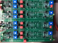
Attached left channel values, could the 10uf in and output caps have anything to do with it?
By the way, did you ever obtain the GPA 604 drivers? I have been drooling over them but never got over the high price caused by customs/shipping/VAT shipped to the Netherlands...
I guess this crossover would work well! View attachment DIY CROSSOVER 6-24.pdf
View attachment 884647
By the way, did you ever obtain the GPA 604 drivers? I have been drooling over them but never got over the high price caused by customs/shipping/VAT shipped to the Netherlands...
I guess this crossover would work well! View attachment DIY CROSSOVER 6-24.pdf
View attachment 884647
Last edited:
I have been running my two way monitors (b&w cm5) with the analog crossover (2 pole) since the weekend and I must say I am very pleased with the result! First thing i noticed is that fading sounds like recording room echos and instruments seem far longer audible!
Measured frequency response is similar to the passive crossover (first order). However, 10k to 20k is rolled off compared to the passive crossover. Any clues on what might cause that?
Up next is trying 4 pole at a lower xover point.
Al this fiddling is in preparation of my first 2 way speaker project with Jbl2450 on yuichi horn (on order) and faital 15pr400[emoji16]View attachment 884373
GO with SL dias for more soft sound
Or radian 1245's? Or even true eXtent[emoji16] First I will try the stock diaphragms. For proper two way config I will have to do my due diligence on which dia is most suitable...
Yes, for 12dB curves, C/2=C, & all Rs the same.
For 24dB, try the following:
HP R1=R3=17k R2=R4=34k, C1=C2=C3=C4=44nF (2x22nF in parallel)
LP R1=R2=R3=R4=34k, C1=C3=44nF, C2=c4=22nF
IME R values vary according to your actual drivers.
If I'll go only for 12dB both in LP and HP, what I have to do with the other cell? Can I let the C and C/2 places empty?
If I'll go only for 12dB both in LP and HP, what I have to do with the other cell? Can I let the C and C/2 places empty?
Yes, empty.

This board is 12dB@500Hz.
Trimpot adjustments were done with oscilloscope & sine waves to match L/R levels electrically, then REW sweeps of each driver to match XO frequency & levels with mic nearfield.
Final fine tuning from listening position (room reflections make difficult to see slope/XO-integration, though).
Then check P1/P2 trimpots to match R values as best possible.
Re-measure, listen, enjoy!
(ignore fact I use different input caps & different values of C on LP vs HP; I'm experimenting. This is my prototyping board).
Last edited:
I'm currently planning one of these. If I know the crossover points and values, can the trim pots be replaced with fixed resistors?
Also, I'll be using these to crossover some full range speakers with a pair of subwoofers. Is there any point to using a slope that follows the speakers natural slope, or should I try a higher xover point and steeper slope? Figured a higher point and slope will make the amp and speakers happier...
Also, I'll be using these to crossover some full range speakers with a pair of subwoofers. Is there any point to using a slope that follows the speakers natural slope, or should I try a higher xover point and steeper slope? Figured a higher point and slope will make the amp and speakers happier...
I'm currently planning one of these. If I know the crossover points and values, can the trim pots be replaced with fixed resistors?
Yes, after you've fine-tuned result with pots. Or install terminal screw blocks you can easily use to swap between different Rs. I still have pots, but already had to replace one that died due to 'too much adjustment'.
Also, I'll be using these to crossover some full range speakers with a pair of subwoofers. Is there any point to using a slope that follows the speakers natural slope, or should I try a higher xover point and steeper slope? Figured a higher point and slope will make the amp and speakers happier...
I cannot comment on this, no personal experience
Yes, empty.
View attachment 884978
This board is 12dB@500Hz.
Trimpot adjustments were done with oscilloscope & sine waves to match L/R levels electrically, then REW sweeps of each driver to match XO frequency & levels with mic nearfield.
Final fine tuning from listening position (room reflections make difficult to see slope/XO-integration, though).
Then check P1/P2 trimpots to match R values as best possible.
Re-measure, listen, enjoy!
(ignore fact I use different input caps & different values of C on LP vs HP; I'm experimenting. This is my prototyping board).
Perfect! Many many thanks!

I'd like to triamp with the tweeter amp getting a balanced signal while the lows and mids get it single ended. Would this require 3 boards? 3 separate power supplies?
Forgive my ignorance.
One more thing. Did the October shipment go on sale yet?
Forgive my ignorance.
One more thing. Did the October shipment go on sale yet?
I have 2 12dB boards sharing one power supply in a 3-way.
Running unbalanced so far; balanced requires (very well matched) duplicate channels & power supply I haven't worked out yet. Alternatively just add an unbalanced-to-balanced module on the output for the tweeter.
Running unbalanced so far; balanced requires (very well matched) duplicate channels & power supply I haven't worked out yet. Alternatively just add an unbalanced-to-balanced module on the output for the tweeter.
Maybe you could go for impedance balancing (which is what balance is all about, if not for two out of phase legs)?
You can add resistance to the grounded side to match the output impedance. See post 267 in the LX Mini crossover thread.
LX-mini Crossover Article
LX-mini Crossover Article
Okay. Thank you solar, Roger and pixel for your replies. I'll post a follow up once I get it to chooch
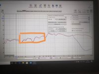
24db gave me best results at 5khz (I could go lower) crossover on my two way monitors, see attached measurements with purple being the midwoofer and red is midwoofer plus tweeter combined.
However, the highlighted region of the midwoofer bothers me! It is there directly coming from preamp as well so xover has nothing to do with it. Unfortunately I do not have measurements of the passive crossover, so dont know if it was there already in the first place.
Any suggestions on how to solve this are welcome..

I get the same suckout around 200Hz. Room effect. Not a lot I can do about it until I get a sub.
I just finished and installed the combination of Wayne's pre amp and Nelson's line level crossover project.
I must say that the combination is simply great...Prior to this, I was using a line level passive crossover using the BOSOZ as pre amp and an L/C network for crossover.
I much prefer the Burning Amp pre amp and Nelsons Line Level crossover...
Can't say why...maybe its the ability to use film/foil caps because the values are so small. Maybe its because I didn't have the proper slopes in my BOSOZ/LC network...at any rate, I am well pleased...
Thanks Nelson...Thanks Wayne..."no work, high pay, all glory"
The whole 100hz-500hz range? I measured 1m from speaker in a small room with a low, sloping ceiling..If your measuring in room it could just be that
- Home
- Amplifiers
- Pass Labs
- DIY biamp 6-24 crossover
