Ok...
I f i understand right i have to set 20 µf instead of 100 uf (9C7/C8). 22 µf will do i hope...the gain with 5x is ok for me.
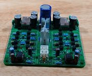
I have tried to make a new pcb...mhmm....i don't know if it satisfy me...
Greets
Peter
I f i understand right i have to set 20 µf instead of 100 uf (9C7/C8). 22 µf will do i hope...the gain with 5x is ok for me.
I have tried to make a new pcb...mhmm....i don't know if it satisfy me...
Greets
Peter
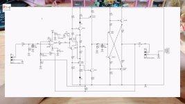
In your schematic, you changed R3 and R6 to 560R. The change should be to the feedback resistors R29, R46 instead. 560R and 22uF works out to 12.9 Hz.
You can use an online RC high pass filter calculator .
You can use an online RC high pass filter calculator .
Last edited:

To those who intend to replace transistors from the kit with something "better":maybe the KSA992 (120V)
and the partner KSC1845
whatch out the codes!
KSA992FATA - hfe 300-470
KSC1845FTA - hfe 300-600
they are cheaper , 100pcs 9,20 euro exl. shipping
Don't throw them away because you'll need them, they are good and adequate.
I have purchased before lots of A992/C1845 but they are complementary just in name, virtually impossible to match. You need to buy more batches to eventually match them. And, by the way, they are very different from BC550/560.
Note that the kit is sealed in a plastic bag, made in the same factory and contains adequately selected transistors. That is why I was able to attain very low THD+N.
Also there are two pairs that should be well matched. You can reconize them easily: they are close to each other, face-to-face. You should select the best match for these two pairs. Then use a bit of thermal paste and place it between these two transistors and use a piece of shrinking tube to join them tightly together. This way they will operate at the same temperature and keep them at the similar hfe value.
Otherwise, you'll end up with "better" transistors and worse sound.
Last edited:
Ok....if i use a calculator i would choose 470 Ohm and 22 uf (15,39 Hz). I think i have done wrong and changed the wrong 100 ohm resistors.
Peter
Peter
I have changed the 100 Ohm to original at the opamp. Also i have changed the feedback resistors on their right place, the value of 560 Ohm remains. 😉
Now i think everything is right...long way because a wrong idea..🙂
Thanks Hifiamp to show me that mistake...
I odered a new pcb now, because i think it is easyer to measure without any components on it. Then a make a new try to design a pcb with KiCad.
Greets
Peter
Now i think everything is right...long way because a wrong idea..🙂
Thanks Hifiamp to show me that mistake...
I odered a new pcb now, because i think it is easyer to measure without any components on it. Then a make a new try to design a pcb with KiCad.
Greets
Peter
I have tested with headphones and different pieces of music....
The LM4562/LME49720 is very similar to the NE5532. Thats my experiance earlier in Phono preamps. It is possible that a measurement shows more.
At last i put an OPA2134 in. Thats great....you can hear everything in the higher frequences better. Its playing cleaned up. Snare, bells sound even better, more present.
I think the OPA2134 is my choice
Peter
I am wondering if it is the original C-3850 schematic or another clone? Maybe @m0rten knows. I have not been able to find a detailed enough pic of the actual PCB. This is the identical circuit layout as ours, with a different op amp (AD797 an "ultralow distortion, ultralow noise op amp" $22.75 USD each, in stock at digikey, lower noise and higher slew rate than a 5532; even lower noise than a 4562) and different transistors. Also, less global feedback with 680R instead of 470R.
The ny gul schematic has a mistake. C22 listed as 10pF. R19 and R37 are reversed.
Looking at the other Ali C-3850 board with the 5534, it is "using low noise small power transistors 2SA733/2SC945, The output tube uses the original UK tube ZTX450 ZTX550." Maybe the @m0rten schematics are older clone boards?
Looking at the other Ali C-3850 board with the 5534, it is "using low noise small power transistors 2SA733/2SC945, The output tube uses the original UK tube ZTX450 ZTX550." Maybe the @m0rten schematics are older clone boards?
Last edited:
First, my apologies for errors in the schematics. Most of them are made for my own pleasure to have a more readable (for me) schematic of PCBs I have bought or that I fancy buying. These schematics may be less scrutinized by me for errors, because I already have BOM and PCB.I am wondering if it is the original C-3850 schematic or another clone? Maybe @m0rten knows. I have not been able to find a detailed enough pic of the actual PCB. This is the identical circuit layout as ours, with a different op amp (AD797 an "ultralow distortion, ultralow noise op amp" $22.75 USD each, in stock at digikey, lower noise and higher slew rate than a 5532; even lower noise than a 4562) and different transistors. Also, less global feedback with 680R instead of 470R.
Some schematics are reverse engineered from PCBs without schematic. I does not enjoy doing that! In these cases chanses are greater for errors, There are not many of these, though, and mostly Xovers, I think.
Lastly, there are the schematics drawn for PCB production. Still not guaranteed 100%, but at least these are more thoroughly checked.
Now, for the C-3850. I do have some boards for this amp, so the schematics are just for my own pleasure. The "ny-gul" (=new-yellow) schematic has indeed errors in it. I did not realize before you guys pointed it out. Thank you! The "green" is a correct version. I hvae now corrected the "ny-gul".
To make this more concrete, here are the 3 PCBs that I have:
Green:
Gul-ny:
Is there an "old yellow"? Yes. No schematic, as it looks like a version of the "green" without input relays:
And no, I don't have technical manual or original schematics on the C-3850.
🙂 morten
Attachments

Good morning Morten
welcome here.
thanks for your effort.
where did you get this big yellow PCB? can´t find it.
chris
welcome here.
thanks for your effort.
where did you get this big yellow PCB? can´t find it.
chris
Back to diyaudio after a bit of a break. Berlusconi did you do your distortion measurements with the C-3850 unloaded or with a load resistor? If no load I would be interested to see the results for 10k and 1k loads. I am a bit baffled by the 1mA quiescent current at the output as that means the preamp will only be happy with high impedance loads. I have some of these boards and will look at the effect of increasing the vas current to 4mA and the output current to 30mA - should be able to drive more demanding loads at possibly lower distortion. Back in the day I designed ( and sold ) an opamp-based headphone amplifier where the first two transistors of the output diamond ran at 3.5mA and the output pair ran at 40mA which would easily drive 32R loads at low distortion. In a way the first diamond buffer+vas in the C-3850 gets you very little except a little more open loop gain. However if you separated the opamp power from the rest of the circuit, using resistors zener diodes, you could use higher supply voltages which will give you more headroom and dynamic range. As well as a preamp the same pcb could then be configured as a headphone amp or small power amp. The engineer in me can't resist tinkering so if you're happy with the preamp as it is you can cheerfully ignore all of my musings, but if anyone is interested I can expand on any of the ideas.
Hi! The shop is on Taobao and is called Pig Sound DIY. This shop also has many other nice PCBs!Good morning Morten
welcome here.
thanks for your effort.
where did you get this big yellow PCB? can´t find it.
chris
For some elaborate designs, you could also check out Best Sound.
🙂 morten
These pages were mainly for Chinese customers, I think.. But now they are targeting the world, seemingly. It was a little mess registering at this site, but for viewing only, I thought there were no problems.
Why don't you try www.taobao.com (or https://world.taobao.com/) only, and then search with this: c-3850 前级
The yellow card shows up in the first page, at least for me.
Good luck!
Why don't you try www.taobao.com (or https://world.taobao.com/) only, and then search with this: c-3850 前级
The yellow card shows up in the first page, at least for me.
Good luck!
- Home
- Amplifiers
- Solid State
- Clon C-3850