I use a blue alps 50k log pot at the input and have no problems. An other pot i had not tried..
Have you done a change on the board ? Original gain ?
Have you done a change on the board ? Original gain ?
Mhmmm...did you ever use someting different at the input, cd player or someting else ? A source with higher output ?
I dont think it is the pot...
No other idea in the moment.
I dont think it is the pot...
No other idea in the moment.
Hi,
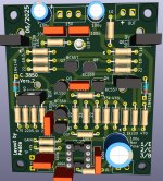
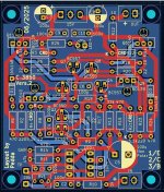
i made another layout for the Mono Clone with BD Transistors. The schematic is the same based on Chalky's simu.
The S8050/8550 transistors are small and need cooling with a heatsink, as i wrote.
Now i have changed to BD139/140 on the pcb. They will need heatsinks too, therefore i set 2,5 mm holes.
I will use heatsinks from Fischer 10022747 SK 95 25 TO220. I think this heatsinks will be big enough to cool down the transistors.
Because there are tracks under the heatsinks, it is useful to put a cardboard disc or a plastic disc betwenn pcb and heatsink for safety.
The heatsinks from fischer have 5mm thicknes after the transistors. Other heatsinks will fit too, but you must use one.
The rest is the same as before...
Greets
Peter
Attachments


send us a pic of your amp, pcb and your changes.Original board, original gain, only power supply more filtered
did you try to change the opamp? -normaly fake chip inside..or lets say it is not a NE5532 or NE5534 😉
kr
chris
I don't have photo in this moment, the board is aliexpress with components in kit, i change Jrc5532 in the kit with genuine NE5532 for more balanced sound, jrc of kit is more harsh with sibilant "S" and non-existent bass, every couple of transistors have same hfc, power amplifier is an inverting 3 x LM3886 parallel, very flat response, 35+35v with 25mf capacitors for each rail, snubber and zobel network, zero hum and noise, speakers 4 ohm.
I have tested many amplifiers with this board, and the sound is poor in bass with medium in evidence respect original signal. I made test with genuine tl072, bass present but soundstage strict, less stereo separation, but not bad.
Example..., i made a simple preamplifier with active tone controls, a couple of ne5532, listening identical sound input/output with flat controls.
excuse me for poor english
Salvatore
Last edited:
Hi Salvatore,
You wrote that you implement a 50k pot and you have a different sound and differnt HF "response". that is the reason i am asking.
As Kleinhorn (peter) wrote that is not normal.
kr
chris
You wrote that you implement a 50k pot and you have a different sound and differnt HF "response". that is the reason i am asking.
As Kleinhorn (peter) wrote that is not normal.
kr
chris
Ok...the bass is poor...There must be something wrong.
I used the orgininal clone as it was delivered. No changes. The bass was ok. I think other users have the same experience.
You write all transistors have the same Hfe. What transistors are in use ?
Have you ever followed my advice and use an other source ? I ask because the output of a phone is very low. If the dac has no higher gain the sound may be poor.
Greets
Peter
Transistors are BC550 BC560, yes same hfe, output dac 2v max, other sources... some CD Philips and Grundig with TDA1540 and TDA1541, more output level respect the chip SABRE ESS 9218P but frequency response is the same.
This evening i can measure voltage of transistor on board, resistors all checked before soldering and perfect value.
This evening i can measure voltage of transistor on board, resistors all checked before soldering and perfect value.
With direct input from smartphone with dac sabre chip no problem, beautiful sound, with 10k bass rolloff, with 50k bass rolloff but less respect 10k, with 100k hf rolloff, that's question
Hi Salvatore,
this behavior is still very strange...
kr
chris
I think like you, but, with 1 opamp and 10 transistors, ultra low distortion on the oscilloscope, great details... but an old 40years age grundig and other brands preamp is much more musical, for me a single opamp has a more natural and balanced sound, i don't agree with the enthusiastic comments based only with oscilloscope and technical report
Hi Salvatore, you are right, without any changes the C3850 sounds as other preamps can do.
But with the changes it is an other preamp. I have no experience until yet, but i think my Mono version with BD transistors will sound great. The pcb's are on their way...
The Mono version with S8050/8550 is good too but the current is a bit high. Perhaps a change of the CRD to lower current is helpful.
The BD transistors can work with 3,2 mA CRD. Thats the reason to make a new layout...
I had a finished preamp from a well known on my table. The pcb was purple. But it seems to base on the same schematic as the green one and the MOFI Clone, sold at Aliexpress.
I only used a 330 ohm resistor to get a bit lower gain. With 100 or 220 ohm i could hear hum. I used the AD797 and it was a different preamp too...
I had to made made more changes, but nothing to do with the pcb. There was a gounding problem.
Greets
Peter
okay...I think like you, but, with 1 opamp and 10 transistors, ultra low distortion on the oscilloscope, great details... but an old 40years age grundig and other brands preamp is much more musical, for me a single opamp has a more natural and balanced sound, i don't agree with the enthusiastic comments based only with oscilloscope and technical report
but id doesnt explain why a pot is changing the rolloff...
enjoy your other preamps
Good, with a new board and BD it can work really in A class, surely other soundHi Salvatore, you are right, without any changes the C3850 sounds as other preamps can do.
But with the changes it is an other preamp. I have no experience until yet, but i think my Mono version with BD transistors will sound great. The pcb's are on their way...
The Mono version with S8050/8550 is good too but the current is a bit high. Perhaps a change of the CRD to lower current is helpful.
The BD transistors can work with 3,2 mA CRD. Thats the reason to make a new layout...
I had a finished preamp from a well known on my table. The pcb was purple. But it seems to base on the same schematic as the green one and the MOFI Clone, sold at Aliexpress.
I only used a 330 ohm resistor to get a bit lower gain. With 100 or 220 ohm i could hear hum. I used the AD797 and it was a different preamp too...
I had to made made more changes, but nothing to do with the pcb. There was a gounding problem.
Greets
Peter
Hi...
It took a little time. I went to holiday and the pcb's have seen half of the world, thanks to dhl....
Yesterday i found the time to solder out the components and solder in on the new pcb's. Why ? The preamp was working with the components and I used matched transistors, wanted to use the matched crd's and so on.
I needed about 3 hours and the boards were finished.
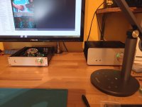
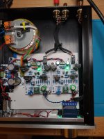
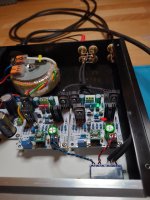
The C3850 Clone is working fine now. The sound is not different using BD139/BD140 instead of S8050/8550. The heatsinks get warm, not hot, you can easily touch.
The first test was with 250 Ohm headphones, Beyerdynamic DT990. As all seems to be ok, i connected my FH9 XRK Mod amp.
No hiss no hum as before, the sound is great....
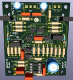
Now...one bad news...i had to find out, that there is a little space problem with the transsistor Q3 and the heatsink of one BD140, Q10 . I have marked on the first picture. My solution was to take a file and work on the heatsink to give a little space to the one solder pad of Q3.
I have made a correction on the pcb and will upload new gerbers. Not a big promblem, but annoys me.
I will not order new pcb's, because with my little change, taking a file, all is fine.
I have to mention that the fischer heatsinks will need 2,5 mm srews to fasten. Under the the heatsinks i used little nylon spacers.
My new pcb will have grounded mounting holes. I moved some components a little bit and some tracks.
I am glad to hved finished this project now...
As i wrote..from VW base to Porsche or Ferrari....😉
Greets
Peter
It took a little time. I went to holiday and the pcb's have seen half of the world, thanks to dhl....
Yesterday i found the time to solder out the components and solder in on the new pcb's. Why ? The preamp was working with the components and I used matched transistors, wanted to use the matched crd's and so on.
I needed about 3 hours and the boards were finished.
The C3850 Clone is working fine now. The sound is not different using BD139/BD140 instead of S8050/8550. The heatsinks get warm, not hot, you can easily touch.
The first test was with 250 Ohm headphones, Beyerdynamic DT990. As all seems to be ok, i connected my FH9 XRK Mod amp.
No hiss no hum as before, the sound is great....
Now...one bad news...i had to find out, that there is a little space problem with the transsistor Q3 and the heatsink of one BD140, Q10 . I have marked on the first picture. My solution was to take a file and work on the heatsink to give a little space to the one solder pad of Q3.
I have made a correction on the pcb and will upload new gerbers. Not a big promblem, but annoys me.
I will not order new pcb's, because with my little change, taking a file, all is fine.
I have to mention that the fischer heatsinks will need 2,5 mm srews to fasten. Under the the heatsinks i used little nylon spacers.
My new pcb will have grounded mounting holes. I moved some components a little bit and some tracks.
I am glad to hved finished this project now...
As i wrote..from VW base to Porsche or Ferrari....😉
Greets
Peter
Attachments
Very nice work. and yes...its a prototype so errors are okay and it is leasson learnt.
Porsche 718 or Porsche 911 😉
Porsche 718 or Porsche 911 😉

Hi,
yersterday i changed the OPA from AD797 to OPA1655. The AD797 sounds better, more details in the mids, sounds more honest. For me the AD797 is the best solution on my boards...
The OPA 1655 is not bad anyway and its cheaper than AD797, but cannot reach the sound of the AD797 in my clone. I will test the OPA1655 in one of my phono preamps . Perhaps it is a replacement for the OPA1611.
Have fun
Peter
- Home
- Amplifiers
- Solid State
- Clon C-3850