No space anymore for more amps. I must offer diiferent amps. The problem is that the people have other listening habits. Boom boxes playing spotify and other ****...
Hifi is not up to date anymore...
On friday is another regulars' table in Münster. I will take my Goldmund clone, Supra II phonopre and one preamp with me...it is not far to walk from the parking area to the bar....
I hope we can hear many pieces of music and have some fun...i have to drive....only one beer 🙁
I will delete the output testpoint...its the same price...🙂
Gerbers with testpoint 🙂
Attachments


My electronic knowlege is not big, but if i can get a correct schematic, i can make a pcb.
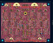
In this case i found the that the feedback tracks are rather far away from input. But i found a middle ground. Right in the middle of the pcb and gave them thicker tracks.🙂
I think "Mofi" thougt the same...dont know is "Mofi" a person oder comany.
Not all of his kits from Mofi are good. Beware of his JC2 clone bcause it is humming and has white noise.
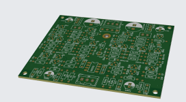
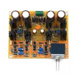
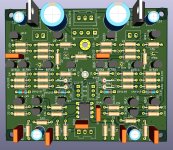
This JC2 clone (first picture) sounds very good without hiss, hum and white noise. I have to test another board (second picture), need the transformators, but ordered....
Peter
In this case i found the that the feedback tracks are rather far away from input. But i found a middle ground. Right in the middle of the pcb and gave them thicker tracks.🙂
I think "Mofi" thougt the same...dont know is "Mofi" a person oder comany.
Not all of his kits from Mofi are good. Beware of his JC2 clone bcause it is humming and has white noise.
This JC2 clone (first picture) sounds very good without hiss, hum and white noise. I have to test another board (second picture), need the transformators, but ordered....
Peter
Attachments
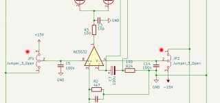
Idea for PCB: Add pads with gap in the two rails to the op amp. With jumpers, the op amp shares the supply. Without jumpers, the op amp could have an independent supply and allow for the option of higher voltages to the rest of the circuit.
Perhaps to complecated to split the ground too...
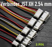
I have found little testpoints with 2,54 mm as by JST too. I hope i find space to set. For more stability I think about 3 pads in one line.
And a new thread
https://www.diyaudio.com/community/threads/clon-jc2.416747/#post-7772515
🙂
I have found little testpoints with 2,54 mm as by JST too. I hope i find space to set. For more stability I think about 3 pads in one line.
And a new thread
https://www.diyaudio.com/community/threads/clon-jc2.416747/#post-7772515
🙂
Now a version with jumpers, 2,5 mm. With a femal connector you can decide which voltage you prefer. PCB/OPA will allow to use the regular voltage from the pcb. OPA/Ext will allow to use a different voltage.
I changend two resistor footprints from vertical to horizontal to get more space.
JST connectors will fit.
Peter
I changend two resistor footprints from vertical to horizontal to get more space.
JST connectors will fit.
Peter
Attachments
Thank you Chris...🙂😊
I searchedin the I Net for JST 3pol, 2,5 mm
https://www.digikey.de/de/products/detail/jst-sales-america-inc/B3B-XH-A/1651046
Thats the Footprint in Kicad i choosed... 😉
Later i will update the gerber files
Greets
Peter
I searchedin the I Net for JST 3pol, 2,5 mm
https://www.digikey.de/de/products/detail/jst-sales-america-inc/B3B-XH-A/1651046
Thats the Footprint in Kicad i choosed... 😉
Later i will update the gerber files
Greets
Peter
Another pcb idea; add TO126 footprints in parallel with the TO92 footprints for the output devices. The user would then have the option of higher output power ( for use as a low impedance heaphone driver for example ) by populating the pcb with TO126 devices and changing the value of the emitter resistors.
Any specific TO126 devices in mind? Should the emitter resistors be paralleled for higher power dissipation?
Toshiba TTA004B
Toshiba TO-126
KSC1381/KSC3503 are good but not available in the same hfe class
or the classic BD140/139_16, or_25
my experience is that the pnp are stronger in hfe- 40-80 more!
Toshiba TO-126
KSC1381/KSC3503 are good but not available in the same hfe class
or the classic BD140/139_16, or_25
my experience is that the pnp are stronger in hfe- 40-80 more!
I am afraid there is no space for a second footprint at the transistors. But it is possible to choose TO126. A BC type will fit in TO126 too.
It is not enough to take the output transistors in TO126 ?
It is possible to change all transistor footprints, but perhaps i can everything draw new, because of different pinouts. Not easy, but possible i think.
Not this week...
I have to rest and other things i have to do... i want to hear my C3850 Clone with an amp now.
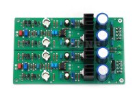
Here is the gerber zipfile, testpoints and JST connectors included.
Peter
It is not enough to take the output transistors in TO126 ?
It is possible to change all transistor footprints, but perhaps i can everything draw new, because of different pinouts. Not easy, but possible i think.
Not this week...
I have to rest and other things i have to do... i want to hear my C3850 Clone with an amp now.
Here is the gerber zipfile, testpoints and JST connectors included.
Peter
Attachments
- Home
- Amplifiers
- Solid State
- Clon C-3850