I purchased the C-3850 the other kit with the 3 piece of relay on the PCB. It has 3 pair input and one pair output.Hi to all
i have seen this pre amp too! 😉
C- 3850 clone pcb
i just ordered the pcb only because i do not trust the components and for me its more work to check and re solder everything.
at the mofi pages it is written that the output voltage is about 22mV on the R22 emitter resistors at the output. i do not believe that this information is correct. it is just 1 mA at the output....this is nonsense.
Please can you measure this ? i guess about 22mA
chris
Unfortunately I do not know how to connect the RCA output,🙄🙄😱
It has two place where possible to connect and really confusing me.
I will post pictures later.
I populated the PCB but I stopped there because of the mentioned problem.
It is really bad (sucks) when information is missing and can not finish the project.
I have other project also (the Krell KSA 50 PCB's) where they did not mark the 3 trimmer pot values just some instruction in Chinese.
To me that does not help at all. Chinese symbols.
Some schematics has only two trimmer pot, others has non. The PCB came without schematics and has 3 trimmers!
Maybe someone has the same C-3850 green PCB and can help me. If yes please....🙂
I Find a picture on the net.
Attachments
Last edited:
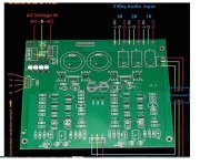
I don't have this kit, but the output is in red below. The RCA jacks are meant to be chassis mount. In that case, use two shielded wires to connect the pads to the RCA jacks. LOUT connects to the center (signal) wire and GND connects to the shield of the wire. Connect the signal wire to the center contact of the RCA jack. I hope this is what you are asking.
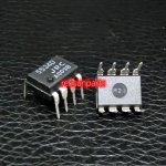
Beeny did a review of this board, and said the 5534 are fake. This was 3 years ago. Not sure if this is still the case. In the video, Beeny has a PCB mount RCA jack installed on the board for testing.

Beeny did a review of this board, and said the 5534 are fake. This was 3 years ago. Not sure if this is still the case. In the video, Beeny has a PCB mount RCA jack installed on the board for testing.
Sorry I was not clear.
The two set of marks for the potentiometer confusing me.
L G R and again L G R all printed on the PCB IN.
If the chip fake I will buy (order from a big company).
I watched one of his video and there he said the chips are OK. His friend also built this kit.
Thank you for your answer.
The two set of marks for the potentiometer confusing me.
L G R and again L G R all printed on the PCB IN.
If the chip fake I will buy (order from a big company).
I watched one of his video and there he said the chips are OK. His friend also built this kit.
Thank you for your answer.
The LGR at the top near the relays connect to the pot at the end terminals. The middle terminal or wiper connect to the input L and R at the bottom in the picture. The G for the input and relay pads should connect to the same terminals on the pot.
When the pot is positioned to the extreme counterclockwise position, the resistance from the wiper to the ground terminal should be zero. When the pot is positioned in the extreme clockwise position, the resistance from the wiper to the ground terminal should be the value of the pot. This insures that volume increases with clockwise turning of the pot.
Important. When soldering to the pot terminals, be sure the pot is turned full clockwise or full counterclockwise.
The only way to know if the parts are genuine is that they will meet specs, especially slew rate. Testing with square waves and oscilloscope is the only way to know for certain. If your kit is 3 years old, it might still be supplied with the fake 5534. These days, the genuine parts are so cheap, it doesn't make sense to substitute fakes. Digikey only has marketplace suppliers for the through hole 5534. Digikey only stocks surface mount 5534.
Last edited:

Thank you!
I have to buy a transformer 18-0-18 V type.
After I will try to set up.
It is not my first neither the second preamp but this one is confusing me a lot. Otherwise it is a nice kit with quality capacitors.
I have to buy a transformer 18-0-18 V type.
After I will try to set up.
It is not my first neither the second preamp but this one is confusing me a lot. Otherwise it is a nice kit with quality capacitors.
Hi ...
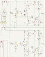
i have corrected the schematic and hope everything is fine now.
I try to design a pcb, but i it will take a lot of time. Cant say how long it will take....
I think it is easyer to buy a new PCB at Ali... 🙂
Chris, do you know where to buy other transistors ? I have taken a look to ZTX types, hard to find to. Other ideas ?
For the first i will change the input ic and let the BC550/560 in there.
Greets
Peter
Attachments
Last edited:
Fine Peter thanks for your effort to design the pcb.
BJT transistors:
NPN
522-ZTX851STZ
PNP
522-ZTX951
they are not cheap!!!
reichelt have them too.
Reichelt ZTX851 ZET
hope this helps
chris
BJT transistors:
NPN
522-ZTX851STZ
PNP
522-ZTX951
they are not cheap!!!
reichelt have them too.
Reichelt ZTX851 ZET
hope this helps
chris
Last edited:
BC327-16 and BC337-16
BC327-25 and BC337-25 are available at mouser and reichelt too.
the y are very cheap!!!
BC327-25 and BC337-25 are available at mouser and reichelt too.
the y are very cheap!!!
Last edited:
if i check the side:low noise bjt, the ZTX851 /951 have less hfe = about 200 hfe
so for bigger hfe you need about 400 --Then you have to buy ZTX1051A / ZTX790A (hfe about 450) voltage about 40V/50V
here is the overview
ZTX618 has just 20V VCE !
so for bigger hfe you need about 400 --Then you have to buy ZTX1051A / ZTX790A (hfe about 450) voltage about 40V/50V
here is the overview
ZTX618 has just 20V VCE !
Attachments
Hi @chermann ,
I have tried the proposed alternatives. Increasing 10p and 100p capacitors reduces bandwidth, as expected, but that doesn't affect behaviour of the circuitry in the audible region. That change could be useful if you anticipate RF interferrences. However, short and adequate cables may prevent that and you still can retain advantages of better frequency response.
I have decided to make just two changes: R1=330 ohm and C8=27pf. Both changes were suggested by Michael Beeny and Ron Schauer in their youtube videos.
Hi Gabor,Unfortunately I do not know how to connect the RCA output
Thats simple. First note that there are three relays for input selection. You may activate individual inputs via relays by shorting VCC with 1#, 2# or 3# inputs. You can do that with multi-position switch.
You right about the RCA connections those are easy. I made a mistake when I asked for help.
It is not the RCA the problem, the potentiometer
It has two places marked bot as IN L G R and again L G R IN.
It should be one L IN and one R IN and one R Out also one L Out.
I will figure it out when it comes to set it up.
Hopefully a signal wrong connection does not damage the pre-amp.
It is not the RCA the problem, the potentiometer
It has two places marked bot as IN L G R and again L G R IN.
It should be one L IN and one R IN and one R Out also one L Out.
I will figure it out when it comes to set it up.
Hopefully a signal wrong connection does not damage the pre-amp.
On the PCB say to use 15 to 18V transformer. Also Benny said 18V optional because the regulator otherwise not even get warm.Thank you!
I have to buy a transformer 18-0-18 V type.
After I will try to set up.
It is not my first neither the second preamp but this one is confusing me a lot. Otherwise it is a nice kit with quality capacitors.
I will see what I find in our local store. Maybe a 16-0-16V if I can get it.
Ah, that was Chinglish, as usual. 😉IN L G R and again L G R IN
But, judging from the number of transistors and ICs it seems to be esentially the same circutry with more input options.
It is important to measure mains voltage first. For example, I have 235 VAC at the socket and I have used 220/15/15 transformer. I have 2X16VAC. With 2X18 transformer, the voltage would have been, in my particular case, 19.2 VAC. A bit higher voltage would just increase heat dissipation at voltage regulators, noting serious.I have to buy a transformer 18-0-18 V type.
Yes, you right.
Sometimes we have over 135 to 137 VAC, yesterday evening I measured it and it was under 120 VAC like 117 VAC. It is not constant, always changing.
Benny said to use 18-0-18 V.
The load is so small it almost does not make almost any difference. The heatsink is cold with 15-0-15 rail voltage.
I will look at the transformer primary also.
Sometimes rated 120 VAC other time 115 V or even 110 V.
Based on that I will decide. I think I will go to the store to pick it up there.
Save the shipping cost unless I order a R Core or Toroidal type from Ali Express.
I don't know if it makes any difference?
The store does not have that, only cheap Chines EI types.
Yes it is the same circuit with 3 input with relays! I like this PCB / kit better bigger board and came with good parts some Elma Silmic.
Referring to @Kleinhorn schematic, with the standard feedback resistors R29, R46 of 100R, the low frequency cutoff frequency (-3dB) set by the 100uF C7, C8 caps is 15.915 Hz. The purpose of these caps is to rolloff gain to unity at DC. If R29, R46 are increased to 1000R, then the cutoff frequency becomes 1.59 Hz. So if the feedback is increased by increasing R29, R46, the value of C7, C8 could be correspondingly decreased to maintain the original 15.915 Hz. With 560R feedback resistors, the caps could be 20uF and get a cutoff of 14.21 Hz.
- Home
- Amplifiers
- Solid State
- Clon C-3850