Chris,Hi Berlusconi
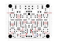
If you look at the voltage diagram at the pcb layout and on the schematics you will find the red marked values and you also can see the resistors value.
so my guess is that on a 22R resistor should have bee a voltage drop about 22mV--> this is just 1mA at the output stage of this pre amp this is nonsense.
kr
chris
Schematics published on Aliexpress and ebay aren't necesarily acurate, quite the contrary.
@chermann I measured the voltages at the test points on a factory assembled board, and all the voltages are correct. 22mV across the indicated 22R resistors. 1mV DC offset at the outputs.

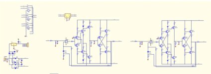
PCB test points.

Schematic supplied with kit/assembled board.

BOM supplied with kit.

Schematic by Michael Beeny.
PCB test points.
Schematic supplied with kit/assembled board.
BOM supplied with kit.
Schematic by Michael Beeny.
Last edited:

It's said to be Class A, but the output transistor seems to be biased too low with only 1mA current. Any fix? Anyone understand how this circuit works? Using the 5532 alone will probably be much better as a line preamp, with much lower distortion.
Last edited:
Exactly @hifiamps.Using the 5532 alone will probably be much better as a line preamp, with much lower distortion.
Just look at the results of distortion measurements I have presented earlier.
Just to make a comparison I have measured again my MBL6100D clone. Results are presented >> HERE <<. One of the measurements (at 1.41 V p-p) is shown on the snapshot below.
Indeed, preamp based on quality opamps ensures much better results. The present "Accuphase" C-3850 clone might be interesting case study but fails to achieve parameters required to be HiFi.
However, MBL610D clone is based on AD797ANZ opamps that cost €19.30 before taxes, more than the complete C-3850 kit. Just 8 AD797ANZ required to build a MBL610D clone cost now 154.40 at Mouser. Purchase decision should be based on cost/benefit consideration.
Please, note that the measurement result below do not correspond to "Accuphase" C-3850
Last edited:
Since I own the board, the next thing to do is listen to it. Yes, it has high distortion, but the distortion is mostly H2. It would be instructive to see how this board fooled an experienced listener like Michael Beeny. He described it as very "neutral" sounding with "great detail". I am sure it must sound pretty good. Was the mistake he made due to the dreaded "expectation bias"? He saw the great wideband performance on the oscilloscope, and knew it must sound good. He is also a fan of the 5532. The problem with this board isn't the 5532, it's the transistor circuit.
You're quite right: increased level of harmonic distortion doesn't authomatically indicate bad sound. This preamp has excellent frequency response and bandwidth. Also, note that it has low distortion at low output level and in normal condition of home listening it must sound good but as soon it crosses 0.35 VRMS, distortion increases signifficantly.
I prefer low distortion because it sounds good with properly mastered recordings. In case of the need for 2nd harmonics I still can use other preamp that injects predominantly that kind of distortion. For example:
https://www.aliexpress.com/item/100....order_list.order_list_main.28.a4211802kuIY5r
I prefer low distortion because it sounds good with properly mastered recordings. In case of the need for 2nd harmonics I still can use other preamp that injects predominantly that kind of distortion. For example:
https://www.aliexpress.com/item/100....order_list.order_list_main.28.a4211802kuIY5r
Good morning
new video by Michael Beeny is available. it is about a similar amp with 4 x NE5534 and balanced board or complete amplifier (housing and transformer...etc..)
new video by Michael Beeny
new kit :new kit 4xNe5534
complete pre amp: complete amp with balanced in/out
have a nice day
chris
new video by Michael Beeny is available. it is about a similar amp with 4 x NE5534 and balanced board or complete amplifier (housing and transformer...etc..)
new video by Michael Beeny
new kit :new kit 4xNe5534
complete pre amp: complete amp with balanced in/out
have a nice day
chris
input filter of this PCB, reference to Beeny schematic
R1 1k and then R2 47k parallel the100pF:
with
R1 1k and 100pF - fg : 1,5915Mhz
recommended by Beeny ? - Why?
R1 1k and 47pF - fg : 3,863Mhz
R1 1k and 27pF - fg: 5,8946 Mhz
my gueuss is that the input filter is too wide open:
with 220pF i got 723400Hz (723kHz)- done at the input filter of FX8 e.g. is enough
so if somebody can try this please- Berlusconi?
thx
chris
the same with the output :
the ouput filter of the opmap is with R23 100R and 10pF C3 --fg : 159Mhz.
With 220pF it if Fg: 7,23MHz should be enough for the "reaction" of the opamp
should be changed too.
if somebody is expert at opamp please be gentle ;-)
chris
the ouput filter of the opmap is with R23 100R and 10pF C3 --fg : 159Mhz.
With 220pF it if Fg: 7,23MHz should be enough for the "reaction" of the opamp
should be changed too.
if somebody is expert at opamp please be gentle ;-)
chris
Just to make a comparison I have measured again my MBL6100D clone. Results are presented >> HERE <<. One of the measurements (at 1.41 V p-p) is shown on the snapshot below.
Indeed, preamp based on quality opamps ensures much better results. The present "Accuphase" C-3850 clone might be interesting case study but fails to achieve parameters required to be HiFi.
However, MBL610D clone is based on AD797ANZ opamps that cost €19.30 before taxes, more than the complete C-3850 kit. Just 8 AD797ANZ required to build a MBL610D clone cost now 154.40 at Mouser. Purchase decision should be based on cost/benefit consideration.
Please, note that the measurement result below do not correspond to "Accuphase" C-3850
View attachment 1346166
You can try the little brothers.
E.g.
AD8599
Now, I have several very busy days until Wednesday and then I will try that. Interesting suggestion.... so if somebody can try this please- Berlusconi?
I think you are correct. This circuit has a distortion generating gain stage (in Class A) outside the feedback loop. It appears to be intentionally done to get a particular sound. Increasing feedback won't get rid of the distortion. Maybe take the output directly from the feedback, and eliminate the gain stage entirely. The Beeny schematic shows feedback coming from the output, but the schematic from the Ali website shows feedback coming before the Class A stage (I think). That would also explain why distortion only improved slightly by increasing feedback, in your measurements. Taking the output from that point would make the preamp inverting, but distortion should decrease considerably. An inverting preamp is not a problem for me (since my source is only digital, which can be easily digitally inverted), but it might be for others.You're quite right: increased level of harmonic distortion doesn't authomatically indicate bad sound. This preamp has excellent frequency response and bandwidth. Also, note that it has low distortion at low output level and in normal condition of home listening it must sound good but as soon it crosses 0.35 VRMS, distortion increases signifficantly.
I prefer low distortion because it sounds good with properly mastered recordings. In case of the need for 2nd harmonics I still can use other preamp that injects predominantly that kind of distortion. For example:
https://www.aliexpress.com/item/100....order_list.order_list_main.28.a4211802kuIY5r
Last edited:
----- IMPORTANT UPDATE ------
My recent measurements indicate that this preamp has indeed low distortion and it indeed achieves HiFi performance.
My previously published measurements in post #26 are wrong: batteries of my sinewave generator run out and it generated distortion, not the preamp.
Now, with fresh bateries I have measured indeed great results. For example, a snapshot below corresponds to 3.500 mV rms at output. At lower output voltages it performs even much better.
This small and cheap preamp really ROCKS!
Measured THD value at 3.500 mVRMS is 0.0026% and THD+N is 0.015%
Once again, I sincerely appologize for causing discomfort by publishing erroneous data.
I hope you can forgive me for causing this inconvenience. 😱
I can say michael bleeny's schematik is correct with two feedback resistors.
I have marked with a red point on the board picture. 33k/470 Ohm went together to the output track, on the other side of the tracks to the 100 uf capacitor in parallel mode.
Michael has the LM4562/LME49720 as its favorit ic. I have in stock. Whats obout the OPA2134 ? I think there is no reason to put an ic in which got a higher price as the whole board...18 Euros....
I think i make a test with both....
Greetings
Peter
Attachments
- Home
- Amplifiers
- Solid State
- Clon C-3850