Sorry... of course 2 x 47000uF = 2 x 47mF🤪 per rail, and 0.1R in between.
It's for a power amp.
It's for a power amp.
I'm confident that this will work, but I'd recommend to measure, if ringing occurs. If you do not want to add resistance as a countermeasure should it ring, you can also add capacitance but only to the 2nd cap bank or lower the capacitance on the first cap bank.
The 159ZJ has 5A max current, if you need more those have 12.5A and are reasonably priced again. I have those chokes 86mF-10mH(0R1)-108mF and no ringing.
The 159ZJ has 5A max current, if you need more those have 12.5A and are reasonably priced again. I have those chokes 86mF-10mH(0R1)-108mF and no ringing.
Attachments
I read this thread with interest, I wondered if I could apply this principal to the power supply for my BA3 fe as preamp.
Having some spare 8x 10.000 uf and would like to use them.
Currently the power supply per channel = 40,000uf / 4x .47ohm / 40,000uf + S/reg.
Could I add L / R / C. prior to feeding the store S/reg, Now comes the really cheeky bit, if this is a sensible, can someone help me out with the values.
Having a separate power supply for the voltage gain stage is probably a really good idea .
The L and R channel of the BA - 3 draws a total of about 100 mA .
I'm no expert , but with 8 x 10,000uF caps , you could consider a C R C R C R C ladder filter .
and forget the inductors completely .
For a value of R = 2R2 , this would give - 68.5 dB 's at 100 Hz and - 72.9 dB at 120 Hz .
This means there would be a 0.66 Vdc drop across all 3 resistors .
.
Last edited:
I read this thread with interest, I wondered if I could apply this principal to the power supply for my BA3 fe as preamp.
To point out , the data sheet for a 2sj74 says the V(br) GDS = 25 Vdc .
Its been my experience with other transistors , that when they spec the break down voltage , there is no margin for forgiveness .
If trimmer P1 of the BA - 3 was being adjusted , the voltage drop across it could end up being 0 Vdc .
Leaving nearly all the voltage rail across drain - source of the 2sj74 .
It would not be a happy moment if that jFET got cooked .
So in my opinion , the maximum voltage for the rails of the BA -3 , should be no more than +/- 25 Vdc .
.
Last edited:
Another perspective is quoted below. For more context see page 6 of the attachment linked.
"The supply voltage is only critical with respect to the voltage rating of the input JFETs, which are nominally 25 volts. In actual testing, they break down around 40 volts. I wouldn't worry about running them as high as 30V. Hot-rodding this circuit would likely involve cascoding the input Jfets to allow higher voltages."
https://firstwatt.com/pdf/art_ba_3.pdf

Hello,
To create a proper filter you will something like the LL1694 or the LL2733. The last one will give you a 100 mH choke with a 3,4 A current rating and 0,85 ohm ohm dcr with the two coils in parallel.
If you have some space and muscles you could also go for the LL2771 with the two coils in parallel ( 2,8 ohm DCR ) but Lundahl can change the airgap so you will have the maximum number of mH . The '' standard one '' is 700mH at 2A. My friend asked a 2,5 A rated one to use in his class A Hiraga 20watt amp. Then 700 will go down to at least 500 mH
Remember CRC is 6 db and CLC is 12 db filter.
Greetings, eduard
Another perspective is quoted below. For more context see page 6 of the attachment linked.
"The supply voltage is only critical with respect to the voltage rating of the input JFETs, which are nominally 25 volts. In actual testing, they break down around 40 volts. I wouldn't worry about running them as high as 30V. Hot-rodding this circuit would likely involve cascoding the input Jfets to allow higher voltages."
https://firstwatt.com/pdf/art_ba_3.pdf
Thanks for investigating this issue .
For a FQP3n30 MOSFET , the data sheet spec says Vgs (th) is 3 to 5 Vdc .
So when the trimmer is set up to bias the FQP3n30 , then it would be safe to run 28 Vdc rails ... when the trimmer is set up .
The danger occurs when trimmer is being adjusted , and the the voltage drop across it could be 0 Vdc .
So if someone wanted to go with 27 or 28 Vdc rails on the BA -3 , consider connecting a resistor in series with the P1 trimmer .
Its an issue to be aware of . It would not be a good moment if the 2sj74 got cooked .
.
Remember CRC is 6 db and CLC is 12 db filter.
Thanks for pointing this out . At first glance , I thought a CLC is a 3 pole filter , but its actually a 2 pole filter .
So a mere mortal can figure out the transfer function , and how to calculate the value of R required to dampen the L .
Which I posted on #134 .
.
I read this thread with interest, I wondered if I could apply this principal to the power supply for my BA3 fe as preamp.
For the power supply of the BA-3 voltage gain stage , consider using a transformer with a dual bobbin .
The advantage of these is that they have low capacitive coupling between the primaries and secondaries .
E core transformers can hum , and r core transformers can be difficult to source .
However, Hammond makes the 229 series , which go up to 48 VA - but you'll need to make a circuit board to mount one .
http://www.hammondmfg.com/229.htm
Also , consider building and connecting a Fo Felix EMI filter .
https://www.diyaudio.com/community/...ilter-for-ac-mains-120-230v-by-folsom.321223/
For the common mode choke , I used a Bourns 8119-RC
https://www.mouser.com/datasheet/2/54/8100_series-777217.pdf
.
Hello,
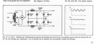
This is the CLC supply used by the French in the eighties for a 50 watt Kaneda class A amp. I used the same choke in my 30 watt Hiraga and my friend used it in his 20 watt Hiraga. It is 200 mH 0,7 ohm dcr. My friend recently changed it into a Lundahl LL2771 but if you are afraid of to much DCR you can also go for the LL2733
The Lundahl is way better than the choke the French used which is maybe just a little bit better than the Hammond ones.
Like i said before you can ask Lundahl to change the airgap ( at no extra cost) so the current rating will be something like 20 % above the actual current so you will have the maximum number of mH. The LL2733 is 100mH at 3,4 A so if you ask them for a 2A model you will get something like a 170 mH which is way better than a 10 mH.
Because the current is not fluctuating in class A i dont expect any ringing. I mean no ringing that will give you a bad sound.
Greetings, eduard
Attachments
Happy New Year everyone
I was going to build a CLC supply but Extreme_Boky got me thinking otherwise.
I wonder if the reason some people don't like CLC is the phase shifting and shift in output impedance around the resonant frequency.
The wise can ponder.
Anyway, I ended up building a CRC supply with some subtle differences.
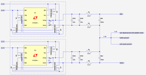
Started with LT4320 rectifier ( a must in my opinion )
Then 2 x 10000µF capacitors ( PEH169 ) with high max ripple current.
I believe that 2 (or 3) 10000µF caps here are better than one 20000µF (or one 30000µF).
This way the high ripple current can be divided by 2 (or 3) capacitors.
I believe that the higher value capacitor you have after the rectifier the more spray of mains harmonics will be poured into the amp.
Then I wanted to try an idea that has been reoccurring in my mind, first time I saw was here I find I get cleaner ground that way ; to split the R in two and have one R on + and one R on ground. The same for minus.
So I put one 0.15Ω on +V and one 0.15Ω on ground line. The same for minus.
After this I put one 100mF with low ESR ( FTcap GW ).
In this position I believe it is better to have one big cap rather than several small ones.
The pcb traces or wiring can make a mess of the current flow to amp and speakers.
Here is a drawing of the supply, the wiring is the same as the drawing.

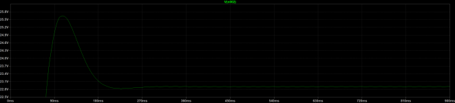
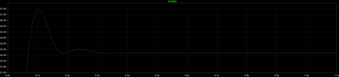
Here is ripple ( measured ) over PEH2 capacitor

And here is ripple ( measured ) over GW1

As you can see we get the desired sinus wave like ripple as we get with the CLC.
By the way, the ripple looks the same with 0.3Ω only on the plus line.
I have just finished an amplifier with this power supply and with 92dB speaker ( Alpair 12p ) there is no sound from the speaker what so ever when amp is idle. I cannot tell if the amplifier is on or off.
Anyway, this is just a CRC power supply my way and it could be an easy test to split the R in two and put half on the ground line.
Here is a photo of the power supply.

rebone
I was going to build a CLC supply but Extreme_Boky got me thinking otherwise.
Somehow I never really liked the sound of CLC. It seems clean-sounding, but details are missing... also, the low-frequency extension could be hit and miss....
I wonder if the reason some people don't like CLC is the phase shifting and shift in output impedance around the resonant frequency.
The wise can ponder.
Anyway, I ended up building a CRC supply with some subtle differences.
Started with LT4320 rectifier ( a must in my opinion )
Then 2 x 10000µF capacitors ( PEH169 ) with high max ripple current.
I believe that 2 (or 3) 10000µF caps here are better than one 20000µF (or one 30000µF).
This way the high ripple current can be divided by 2 (or 3) capacitors.
I believe that the higher value capacitor you have after the rectifier the more spray of mains harmonics will be poured into the amp.
Then I wanted to try an idea that has been reoccurring in my mind, first time I saw was here I find I get cleaner ground that way ; to split the R in two and have one R on + and one R on ground. The same for minus.
So I put one 0.15Ω on +V and one 0.15Ω on ground line. The same for minus.
After this I put one 100mF with low ESR ( FTcap GW ).
In this position I believe it is better to have one big cap rather than several small ones.
The pcb traces or wiring can make a mess of the current flow to amp and speakers.
Here is a drawing of the supply, the wiring is the same as the drawing.
Here is ripple ( measured ) over PEH2 capacitor
And here is ripple ( measured ) over GW1
As you can see we get the desired sinus wave like ripple as we get with the CLC.
By the way, the ripple looks the same with 0.3Ω only on the plus line.
I have just finished an amplifier with this power supply and with 92dB speaker ( Alpair 12p ) there is no sound from the speaker what so ever when amp is idle. I cannot tell if the amplifier is on or off.
Anyway, this is just a CRC power supply my way and it could be an easy test to split the R in two and put half on the ground line.
Here is a photo of the power supply.
rebone
Attachments
Rebone , Looks Great . Thanks for sharing your experiences .
" I wonder if the reason some people don't like CLC is the phase shifting and shift in output impedance around the resonant frequency.
The wise can ponder. "
Someone else brought up the issue of phase shift caused by the power supply filter . So I asked FAB this very question .
Hope FAB is OK with me quoting him , but he said " phase angle of the power supply is not a parameter I look for . "
With a CLC power supply filter , if the L is not correctly dampened , even though the resonance is at quite a low frequency ,
if there are sudden current demands , there will be ringing issues . I am absolutely no expert , but this explains why a CLC power supply filter
is good with Class A amps that have a follower output stage and are biased quite high .
Where as with a class A/B amp , current demands vary quite a bit , so either use a CRC filter OR a CLRC filter making sure the L is correctly dampened .
.
Underhill, Thanks for your reply.
I am no expert either, but I did quite a few simulations and studies on CLC earlier in this thread, so I do agree on the ringing and dampening.
Some of the amplifiers on this forum run class A at say 1 Ampere and then deliver say 5 Ampere in class AB at lower loads, say 4Ω.
I think that one of the main benefits of CLC is the sinus wave like ripple that it delivers.
This way we can have the same sinus wave like ripple using CRC.
The steep rise of a saw tooth ripple contains a lot of high frequency noise that is good to try and stop before it enters the amplifier.
Anyway, just my thoughts and it seems to work very well.
rebone
Have you guys considered LCC, or LCRC instead of capacitor input choke supply, for class A power amp?
Any pro and cons?
Any pro and cons?
Supply filters that lead with a choke, such as LCC or LCRC are sometimes referred to as "swinging choke" filters. Their main characteristic is the final voltage is 0.9 * secondary AC, instead of 1.4 (nominal, but realistic 1.3) * secondary AC. However the final voltage only settles to 0.9 after the amp is fully warm and drawing its final bias current. Prior to that, it is possible for components of the filter and amplifier to see the full 1.4 factor, and those components should be rated for the higher voltage.
I don't recall what the stated advantage of a swinging choke filter is supposed to be. Perhaps a final lower voltage might be advantageous in some circumstances, maybe for a high voltage vacuum tube amp. For the lower voltage Class A amps that we typically discuss here, I cannot think of an advantage.
I don't recall what the stated advantage of a swinging choke filter is supposed to be. Perhaps a final lower voltage might be advantageous in some circumstances, maybe for a high voltage vacuum tube amp. For the lower voltage Class A amps that we typically discuss here, I cannot think of an advantage.
Have you guys considered LCC, or LCRC instead of capacitor input choke supply, for class A power amp?
Any pro and cons?
Here is good article concerning a LC power supply filter . Note the equation for Vdc .
I've never built one , so I can't say anymore than this .
https://electronicscoach.com/choke-filter.html
.
- Home
- Amplifiers
- Pass Labs
- CLC vs. CRC