Fantastic. Thank you!
Couple of dummy questions: I always though the R was to go in parallel . But in series you say, new to me and so I guess I gotta read on 🙂
Then, given 147.000uF after each L (my case), let me ask it practically: is there any point whatsoever in considering daming that ringing?
Regards,
Andy
Yes , the R is connected in series with the L to dampen it .
The equation says the dampening R required is proportional to sqrt ( L / C2 )
The good news is that your C2 is a massive 147 mF - so this will lower the value of R required to dampen the L .
If you are using the Hammond 159ZL , plugging the numbers in , that gives a value of 0R37 required
but r = 0R16 for the 159ZL , so connect 0R2 in series with it .
I have read people using a Zeta as low as 0.5
Which means you could try a value as low as 0R1 in series to dampen the L .
I'm an absolutely no expert , but if you're amp requires sudden current demands , then yes , I suspect the dampening is necessary .
I usually don't like analogies , but the shock absorbers on a car provide the dampening .
If you've ever driven a car , with no shock absorbers , and hit a pot hole , the car will oscillate up and down .
The amount of time for the car to stop oscillating is called the settling time .
.

Thank you, again!
Was just now doing the maths myself. Yes, 0R2 should be a feasable installation. May need to rearrange a couple of things, depending on resistor dissipation demands.
No sudden current demands, luckily, an Aleph J (Zen mod variant) with CCS. Biased at approx 1A9 per rail. But, the PSU was originally planned for a BA-3, and that amp does have sudden current demands.
Will dig up my old resistor dissipation calculating skills (my old=from the textbook I don’t own ) and look at the alternatives. Perhaps I’ll just parallell two 5 watt 0R4 resistors, but maybe even 3 watts will do, but run a bit hard in the long term.
Just saw a pic of my PSU in post #119 in this thread. You can see the L connected by wire to the first post filtering cap, that’s the point needing reconfig.
Was just now doing the maths myself. Yes, 0R2 should be a feasable installation. May need to rearrange a couple of things, depending on resistor dissipation demands.
No sudden current demands, luckily, an Aleph J (Zen mod variant) with CCS. Biased at approx 1A9 per rail. But, the PSU was originally planned for a BA-3, and that amp does have sudden current demands.
Will dig up my old resistor dissipation calculating skills (my old=from the textbook I don’t own
) and look at the alternatives. Perhaps I’ll just parallell two 5 watt 0R4 resistors, but maybe even 3 watts will do, but run a bit hard in the long term.Just saw a pic of my PSU in post #119 in this thread. You can see the L connected by wire to the first post filtering cap, that’s the point needing reconfig.
I am no expert by a long shot either and was afraid of ringing based on simultions too.
Measurements on the real thing showed that there was no ringing at all and I did not need any additional dampening.
Thankfully with digital scopes the transient response can readily be captured.
Measurements on the real thing showed that there was no ringing at all and I did not need any additional dampening.
Thankfully with digital scopes the transient response can readily be captured.
I figured highes dI/dt would be on turn on. Somebody more competent later suggested to measure while the amp is putting out a square wave into a dummy load, which I haven't done yet. Just sayin' it might be worth to measure, if damping is necessary, as additional resistance is not necessarily desirable.
Last edited:
suggested to measure while the amp is putting out a square wave into a dummy load, which I haven't done yet. Just sayin' it might be worth to measure, if damping is necessary, as additional resistance is not necessarily desirable.
Zeta is usually set to 0.707 to correctly dampen the L .
For Zeta , I have read people using a value as low as 0.5
which will significantly lower the value required for the dampening resistor .
Anynor has used a massive value for C2 , which will also lower the value required for the dampening resistor .
.
The way to calculate this is as a pi-section constant-k network. Basically you treat the capacitors as being in series across the inductor for the purposes of the calculation.
it seems to me that the L values through this thread are two orders of magnitude too low. For example the example above of 33mF-25mH-33mF has a resonance at 250Hz. Which means it isn’t even filtering ripple.
I fixed a Leak Stereo 60 a few years ago with the original 0.3H choke. They fixed it later to at least 3H, and so did I. The original resonance was at 72Hz. Not very useful in a PSU.
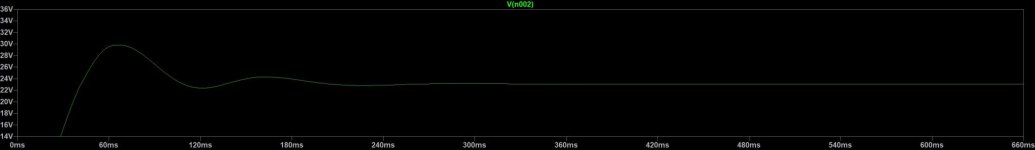
I just ran some numbers for a CLC LPF power supply filter using microcaps software .
Hopefully , this is correct . r = 0.044 and there was no dampening resistor .
For a power supply C1 , L , C2 filter
fo = 1 / ( 2 x Pi x sqrt ( L x C2 ))
==================================================
C1 = 44 mF , L = 2.5 mH , C2 = 44mF
fo = 15Hz
- 33 dB @ 100 Hz
- 36 dB @ 120 Hz
===================================================
C1 L = 10 mH , C2 = 147mH
fo = 4.1 Hz
- 54.5 dB @ 100 Hz
- 57.3 dB @ 120 Hz
====================================================
C1 = 33 mF L = 25 mH C2 = 33 mF
fo = 5.5 Hz
- 51 dB @ 100 Hz
- 54 dB @ 120 Hz
====================================================
Andynor 's power supply CLC filter is looking pretty good .
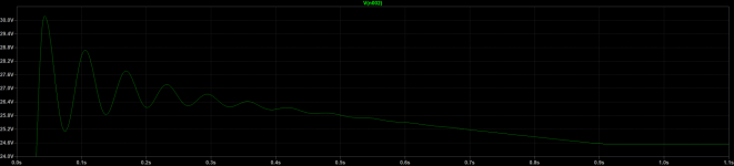
And this is what the ringing with the resonant frequency is supposed to look like according to simulation.
However with all the parasitic effects of real life parts, I have seen none of that in practice even though my Pi filter should be underdamped and therefore ringing. It could be possible that my connections between parts are that bad that they introduce enough contact resistance to dampen the ringing, but then the voltage drop should be higher.
However with all the parasitic effects of real life parts, I have seen none of that in practice even though my Pi filter should be underdamped and therefore ringing. It could be possible that my connections between parts are that bad that they introduce enough contact resistance to dampen the ringing, but then the voltage drop should be higher.
Attachments
for proper analysis, you need to introduce all life parameters - that includes also xformer data
best tool (for us just scratching real knowledge) is Duncan's PSUD2
what I made (I believe I posted links previously) is not showing anything to worry about, be it used with amp having instantaneous full Iq, nor with amps needing 60s to have full Iq
and I'm sure in quality of all connection points
best tool (for us just scratching real knowledge) is Duncan's PSUD2
what I made (I believe I posted links previously) is not showing anything to worry about, be it used with amp having instantaneous full Iq, nor with amps needing 60s to have full Iq
and I'm sure in quality of all connection points
And this is what the ringing with the resonant frequency is supposed to look like according to simulation.
However with all the parasitic effects of real life parts, I have seen none of that in practice even though my Pi filter should be underdamped and therefore ringing. It could be possible that my connections between parts are that bad that they introduce enough contact resistance to dampen the ringing, but then the voltage drop should be higher.
Ozofis , Thank you for simulating this . For an underdamped system , the ringing will occur when there is a sudden demand for current .
I usually don't like analogies , but if you have ever driven a car without shock absorbers , and hit a pole hole ( step function ) ,
the car will oscillate ( ring ) and then there is a settling time - as your graph shows .
As I recall , a resistive load will help to dampen the L . So for your simulation , suggest changing the 6 ohm load to a CCS .
Yes I was protoyping an amp drawing 1.3 Amps , and was using 18 awg (?) lamp cord from the power supply to the amp ,
and it was a bit surprising to see a 12 mV drop across a 40 cm bit of wire .
So keeping the impedance down in the power supply wiring is critical - I'll probably use 12 awg for the build .
.
https://www.diyaudio.com/community/threads/clc-vs-crc.337738/post-7002200For an underdamped system , the ringing will occur when there is a sudden demand for current .
" Yes, we are interested if there is any ringing at CLC output on load change, or what transient response looks like. I’ve set up test case with
CLC as 33 mF – 25 mH/0.9 Ω – 33 mF. As chokes were used secondaries of two smaller transformers. As load was used current sink governed by signal generator (my standard test equipment for power supplies). Load was 5 A peak to peak at 1 kHz and limited rise time to stay within possible speed of change for the real audio signal.
Test reveals that there is absolutely no ringing and response is clean. Response using 65 mH/0.3 Ω was the same (ripple was cut by half). "

" Most interesting fact may be that CLC transient response was exactly the same as with CRC consisting of 33 mF – 0.33 Ω – 33 mF.
My conclusion is that with choke we get much lower ripple and less voltage sag at very low frequency load. But, from several hundred Hz and up, performance of PS completely depends on output capacitor and is exactly the same for CRC or CLC. "
Tombo - Great Test - Thanks for going to all the effort of creating an actual test set up .
... and you have used a current sink as the load ... which I think is correct .
Approaching this with a transfer function , and grinding out the algebra , plugging in the numbers of 33 mF - 25 mH 0R9 - 33 mF ,
I think this will give a Zeta = 0.52
Recall , with an ideally damped system Zeta = 0.707 . However , your actual test set up shows its possible to get
away with an under damped system when Zeta = 0.52
.
Its kind of interesting the different approaches to solving this 1) simulation 2 ) an actual test set up 3 ) with math
.
CLC as 33 mF – 25 mH/0.9 Ω – 33 mF. As chokes were used secondaries of two smaller transformers. As load was used current sink governed by signal generator (my standard test equipment for power supplies). Load was 5 A peak to peak at 1 kHz and limited rise time to stay within possible speed of change for the real audio signal.
Test reveals that there is absolutely no ringing and response is clean. Response using 65 mH/0.3 Ω was the same (ripple was cut by half). "
" Most interesting fact may be that CLC transient response was exactly the same as with CRC consisting of 33 mF – 0.33 Ω – 33 mF.
My conclusion is that with choke we get much lower ripple and less voltage sag at very low frequency load. But, from several hundred Hz and up, performance of PS completely depends on output capacitor and is exactly the same for CRC or CLC. "
Tombo - Great Test - Thanks for going to all the effort of creating an actual test set up .
... and you have used a current sink as the load ... which I think is correct .
Approaching this with a transfer function , and grinding out the algebra , plugging in the numbers of 33 mF - 25 mH 0R9 - 33 mF ,
I think this will give a Zeta = 0.52
Recall , with an ideally damped system Zeta = 0.707 . However , your actual test set up shows its possible to get
away with an under damped system when Zeta = 0.52
.
Its kind of interesting the different approaches to solving this 1) simulation 2 ) an actual test set up 3 ) with math
.
Although damping factor is not ideal, no ringing occurred as transient load was with realistically limited dI/dt. Likely, with short rise time square load, there would be some ringing.
I would encourage anyone with an oscilloscope, signal generator, dummy load for distortion measurements and amplifier with CLC power supply to take a measurement with square wave signal at amplifier input. That will provide square wave load on PS output and oscilloscope will show what happens. If several members do that, I think we will have a proper answer. 🙂
I would encourage anyone with an oscilloscope, signal generator, dummy load for distortion measurements and amplifier with CLC power supply to take a measurement with square wave signal at amplifier input. That will provide square wave load on PS output and oscilloscope will show what happens. If several members do that, I think we will have a proper answer. 🙂
I read this thread with interest, I wondered if I could apply this principal to the power supply for my BA3 fe as preamp.
Having some spare 8x 10.000 uf and would like to use them.
Currently the power supply per channel = 40,000uf / 4x .47ohm / 40,000uf + S/reg.
Could I add L / R / C. prior to feeding the store S/reg, Now comes the really cheeky bit, if this is a sensible, can someone help me out with the values.
Having some spare 8x 10.000 uf and would like to use them.
Currently the power supply per channel = 40,000uf / 4x .47ohm / 40,000uf + S/reg.
Could I add L / R / C. prior to feeding the store S/reg, Now comes the really cheeky bit, if this is a sensible, can someone help me out with the values.
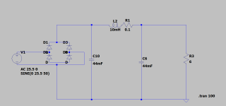
Not sure if this will do much in a preamp with a superregulator as the reg probably has pretty high ripple rejection. The current draw from the preamp is around 250 mA so probably no worries regarding ringing during operation. You could try the popular Hammond 159ZJ or any choke so that the product C(mF)*L(mH) > 100.
Simulation says again that it would ring on startup, when the big caps are charging, but I bet in reality it'll be fine. The opamp in the Superreg seems to be rated up to 36V and if the caps are too it'll survive even with ringing. Increasing C or L will increase the ringing, increasing the choke's DC resistance will reduce the ringing.
The 159ZJ is 10mH and 0R16. If you have anything similar around disconnect the superreg, put the choke in instead of the resistors and measure if it rings on startup with emtpy caps. If it rings, add resistance in series with the choke until it doesn't.
Attachments
Hi,
I'm often thinking about to try a CLC psu, I have only CRCs until now, with 0.33-0.47 mF + 0.1R + 0.33-0.47 mF.
I would replace the 0.1R resistor with the 159ZJ - would it work properly?
Thanks in advance for any hint.
I'm often thinking about to try a CLC psu, I have only CRCs until now, with 0.33-0.47 mF + 0.1R + 0.33-0.47 mF.
I would replace the 0.1R resistor with the 159ZJ - would it work properly?
Thanks in advance for any hint.
- Home
- Amplifiers
- Pass Labs
- CLC vs. CRC