It looks tempting to add decoupling caps at FW or ZM’s designs. As is, ground wire from one channel PCB is practically only for voltage reference. Only small current, with small variations flows through it. Actual current to the ground flows only through load. So, amp PCB ground is kept at real ground level with minor variation.
Adding decoupling capacitor will run transient currents through this reference ground and will increase (due grounding wire resistance and inductance) variation of actual amp PCB ground potential. I’m not sure if this could cause a real degradation of output signal or is only a theoretical difference.
If this is a real problem, solution could be a separate grounding wire for decoupling capacitors.
As is, ground wire from one channel PCB is practically only for voltage reference.
Yeah ... clever solution, as to be expected, would not mess with that
I agree with you 100%.Could be worthy of a mod as some peolple think that's the most important cap in the amp 😉
It looks tempting to add decoupling caps at FW or ZM’s designs. As is, ground wire from one channel PCB is practically only for voltage reference. Only small current, with small variations flows through it. Actual current to the ground flows only through load. So, amp PCB ground is kept at real ground level with minor variation.
Adding decoupling capacitor will run transient currents through this reference ground and will increase (due grounding wire resistance and inductance) variation of actual amp PCB ground potential. I’m not sure if this could cause a real degradation of output signal or is only a theoretical difference.
If this is a real problem, solution could be a separate grounding wire for decoupling capacitors.
Agree with you as well, on all accounts.
The ground fill on Aleph J PCB is there to set the gain/input impedance (220 Kohm resistor that actually creates input signal voltage variations that are amplified), and to provide a current return for two LEDs. I used this provision (for 2 LED) and tried a few decoupling capacitor values, together with additional wide ribbon paths towards a common point, to lower return path impedance to the ground... with absolutely fantastic results. But, to do this properly, a new PCB design will be required. In the end, I settled with very short DC & speaker cables' wiring and a combination of decoupling capacitors placed on the PS PCB. It is far from ideal, but the result is very good indeed. Just a little warning here.... if the local decoupling is not done right, it can cause instability and oscillations.
I tried Hammond 159ZJ 10mH / 5A chokes... but I did not like the end result. Initially, the impression was positive... but after a long listen I concluded that the harmonic structure was not what I'd expected to hear. I could not get the bass to sound right with chokes.... it was clean... but it did not have an attack. The whole sound was too nice, too polished for my liking.... and then after a week of casual listening... it became tiring and disruptive.
I will definitely build another Aleph J.... (this one will also be a DC coupled with no overcurrent protection type 🙂) as soon as my workload and family obligations allow. But this time, I will use a discrete power supply (no PCBs) and the AMP PCBs will have provision for local voltage rails' decoupling, with correct routing back to PS common.
and then after a week of casual listening... it became tiring and disruptive.
... and then you went back to CRC?
May I ask what value C, R, C you are using.
Yes, I went back to CRC. The second (last) C was paralleled (at various points on the PS PCB) with a few caps... just to get me the sound I like.
The CLC may also be a perfect solution for many amps and many systems/tastes. The bottom line is that an amp kind of requires fine-tuning in the end, to blend nicely with the rest of the system.
The CLC may also be a perfect solution for many amps and many systems/tastes. The bottom line is that an amp kind of requires fine-tuning in the end, to blend nicely with the rest of the system.

But this time, I will use a discrete power supply (no PCBs)
I will be using a hardwired PSU as well, mainly because I will be using screw terminals.
Also, I think it is easier to direct where the currents go with hardwiring.
This seems to be a good approach for the wiring.
After the rework of wiring it is the quitest (concerning hum) amplifier I have built yet.
Have a look here: https://www.diyaudio.com/community/...ated-build-guide.241729/page-424#post-7016728
... and in particular -> here: https://www.diyaudio.com/community/...ated-build-guide.241729/page-424#post-7016741
... and in particular -> here: https://www.diyaudio.com/community/...ated-build-guide.241729/page-424#post-7016741
I did and it works - many thanks!Perhaps you should consider a CLCC instead of CLCRC.
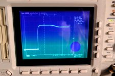
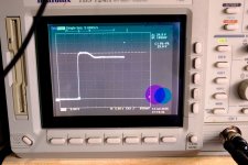
It was: 86mF-10mH(0R1)-54mF-0R08-54mF
and now is: 86mF-10mH(0R1)-108mF
I could not measure any ringing on both and now have a bit less PSU impedance.
Attachments
I found these available in the UK that I may try out.
https://www.cybermarket.co.uk/shop/speaker-building/crossover-network-coil.html
https://www.cybermarket.co.uk/shop/speaker-building/crossover-network-coil.html
Have you spotted these? I bought a pair but have yet to finish that particular board.
https://www.ebay.co.uk/itm/324953900952
https://www.ebay.co.uk/itm/324953900952
Thanks for that. They look good bits of kit. A bit more money than I'd like compared to those I shared but I'm sure they are very suitable for the job.
But isn't the ripple higher than before? Seems the filter is not as low pass that way...It was: 86mF-10mH(0R1)-54mF-0R08-54mF
and now is: 86mF-10mH(0R1)-108mF
I could not measure any ringing on both and now have a bit less PSU impedance.
It should be, but I measured around 3mV (this is all frequencies RMS) as before with a load of 4.8 A . Noise from one channel was around my measurement threshold of 0.08mV. Balanced noise was around 0.13 mV same as before. The only noticable difference I measured was 0.4 V more Voltage.But isn't the ripple higher than before?
I bought those coils, when they were still cheap: Triad C-60U
and shielded them with something like this (the exact same model (110*100*115mm) I had seems to be no longer available): Shield
Last edited:
Which of the following inductors would you choose (if any) for use in a CLC power supply?
What about other alternative recommendations?
- Hammond 159ZJ (10 mH; 160 mΩ)
- Erse ESQ55-14-10000 (10 mH; 257 mΩ)
What about other alternative recommendations?
Somehow I never really liked the sound of CLC. It seems clean-sounding, but details are missing... also, the low-frequency extension could be hit and miss.... a lot will depend on how long the choke wires are/ PCB traces width & length.Which of the following inductors would you choose (if any) for use in a CLC power supply?
- Hammond 159ZJ (10 mH; 160 mΩ)
- Erse ESQ55-14-10000 (10 mH; 257 mΩ)
What about other alternative recommendations?
CRC was always my preferred choice; with high-quality wire-wound resistors. The Panasonics commonly used, have outstanding reliability... but I do not like how they sound. Wire-wound resistors have better sound (more natural, better extension top to bottom) but are prone to fail-open.
Also, there's no way I could suggest a solution that will suit your needs / your system / your taste... try them all and see what's best for you.
I use those Hammonds. I am very happy.Which of the following inductors would you choose (if any) for use in a CLC power supply?
- Hammond 159ZJ (10 mH; 160 mΩ)
- Erse ESQ55-14-10000 (10 mH; 257 mΩ)
What about other alternative recommendations?
Approx 300.000uF after the chokes per chan.
Attachments

- Home
- Amplifiers
- Pass Labs
- CLC vs. CRC