Boyz, real life is what it counts; build it then measure
Duncan's PSUD is great program, but it is always as good as operator is predicting real life situation ........ which means ...... well - it means that one must cover absolutely every possible characteristic not just of elements in PSU itself, but also every possible characteristic of load (amplifier) itself ...... not just taking in account V and A but also time ........ rare are the amps biased in millisecond - having full Iq instantly
that saying, by my experience, PSUD was always smarter than me

It’s possible that there is such low frequency voltage ringing on load change with very high choke inductance. But, taking in the account difference between simulation and measurement taken on the real circuit, it could be not present.tombo56
Interesting to see what happens on the rail with your 65 mH/0.3 Ω choke.
Yup, as ZM said, build and measure. 🙂
SPICE simulation is for proof of concept.
Thanks for trying to keep us real Zen Mod 🙄
It's just little me trying to find my feet.
I've used PSUD a bit, but it sounds like there is a lot more to it.
I have wanted to build a new amp for quite a few years and never had the time until now.
In the process I've ended up with a few boxes with parts for amps I was going to build.
I would like to buy right this time, specially chokes that are a bit more expensive here than in your neighbourhood.
I guess that if you want to try something, you just turn around and find what you need in one of your drawers, just like a friend of yours that carries the name of this part of the forum. 😏
I hope you can put up with us for a little while longer.
I'm not sure why you think that those of us looking at sims don't allow for transformer source impedance. I certainly have included it - it would be hard to sim a PSU without a transformer! Incidentally, when I sim the PSU that you describe, I don't see any ringing on the voltage across the load - in fact the output voltage result looks very like your screenshot.For comparison between sim and real circuit, here is startup voltage waveform of 33 mF – 25 mH/0.9 Ω – 33 mF CLC supplied by 300 VA transformer. It’s evident that there is no voltage overshot. Transformer was directly plugged to mains (no soft start).
Simulation has ideal voltage sources, so it would be better to add supply internal resistance as 0.1 to 0.2 Ω.
View attachment 1048100
oh no, I'm not trying to spoil your fun .... just saying that sometimes easiest way of learning is to actually try it in vivo ...... that way getting better picture what's really happening and then it's easier later to know what's important in simulations
initial ringing is not big issue if parts choice is not result of too much greed
in case of PSU I linked as example - I did not go for stratospheric huge inductances - knowing that decent number properly made is much better than choke on steroids - big L but only for small range of currents
in other words, I did go with 4m7H, but with predicted Rdc and also current range; whats written on them is "max 2A" but that's nominal value
anyway - I can't see any significant ripple under nominal amp Iq, chokes are cold, same as caps ....... same as diode bridges
frankly - didn't waste any time in sims, having enough xperience with CLC filters from before - exactly with chokes pulled from various old equipment ; as long resonant frequency is under audio range , you're probably good
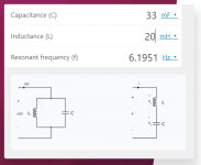
edit: tried to write formula properly but typing sign of sq. root is always recipe for disaster , for me
with mine - 4m7H and 33mF, I'm slightly above 10Hz and that's just simple calc - not sims , so without including ESR of caps and Rdc of chokes and also fact that CLC is in question , so Pi filter - not just L filter cell
point being - I'm thinking - when you're close enough, just grab it; math involved is anyway over my head
initial ringing is not big issue if parts choice is not result of too much greed
in case of PSU I linked as example - I did not go for stratospheric huge inductances - knowing that decent number properly made is much better than choke on steroids - big L but only for small range of currents
in other words, I did go with 4m7H, but with predicted Rdc and also current range; whats written on them is "max 2A" but that's nominal value
anyway - I can't see any significant ripple under nominal amp Iq, chokes are cold, same as caps ....... same as diode bridges
frankly - didn't waste any time in sims, having enough xperience with CLC filters from before - exactly with chokes pulled from various old equipment ; as long resonant frequency is under audio range , you're probably good
edit: tried to write formula properly but typing sign of sq. root is always recipe for disaster , for me
with mine - 4m7H and 33mF, I'm slightly above 10Hz and that's just simple calc - not sims , so without including ESR of caps and Rdc of chokes and also fact that CLC is in question , so Pi filter - not just L filter cell
point being - I'm thinking - when you're close enough, just grab it; math involved is anyway over my head
Last edited:
I'm not sure why you think that those of us looking at sims don't allow for transformer source impedance. I certainly have included it - it would be hard to sim a PSU without a transformer! Incidentally, when I sim the PSU that you describe, I don't see any ringing on the voltage across the load - in fact the output voltage result looks very like your screenshot.
I was only referring to the rebone’s sim, not to all members in general and all the sims. How did you get that impression?
By V1 – V3 voltage sources it is not written Rser = xx, so it was a valid assumption.
I was only referring to the rebone’s sim, not to all members in general and all the sims. How did you get that impression?
By V1 – V3 voltage sources it is not written Rser = xx, so it was a valid assumption.
Well, your post 59, which I was replying to, didn't mention rebone. But I apologise if I misunderstood you. Thank you for posting your test results.
Well, your post 59, which I was replying to, didn't mention rebone. But I apologise if I misunderstood you. Thank you for posting your test results.
No need for apology, I see now it could be interpreted that way you did.
Hard to think of fine details while just pushing “Post reply” button. 🤣
tombo56
You were correct, for some reason ( I know why, but not important ) my trafo impedance was 1µ.
I have changed it to 150mΩ and your 20mH/0.9Ω choke sims just like your screenshot.
With your help my sim sims more correct, thank you for that.
I will build and meassure when I get that far.
Moving country resently, I left behind my old large scope, and need a new one.
Preferably a pc scope for space reasons.
May I ask what model you Hantek is?
Excellent, now there are two simulations that correspond to the real circuit results, from you and ianbo. Now, you can more trust results with other inductor values.
My scope is Hantek DSO 1062B, literally a very “handy” device.
My scope is Hantek DSO 1062B, literally a very “handy” device.
Hi Zen Mod
your input is aways welcome
The current rating of chokes puzzles me a bit.
A 25watt class A biased at 1.7A amp into 4Ω will draw more than 2A peak current.
We don't have to account for that peak current?
Will a 10A rated choke be a less suited choice?
Also, say a 2.5mH rated at 10A will have more inductance if run at 1.5A, but by how much? ( maybe not so important )
So much to learn, but so little time.
( I will keep simming a bit more to try and learn whats going on, but don't tell anyone 😉 )
your input is aways welcome
big L but only for small range of currents
The current rating of chokes puzzles me a bit.
A 25watt class A biased at 1.7A amp into 4Ω will draw more than 2A peak current.
We don't have to account for that peak current?
Will a 10A rated choke be a less suited choice?
Also, say a 2.5mH rated at 10A will have more inductance if run at 1.5A, but by how much? ( maybe not so important )
So much to learn, but so little time.
( I will keep simming a bit more to try and learn whats going on, but don't tell anyone 😉 )
tombo56
I did a new sim with your 65mH/0.3 with the new trafo impedance.
A bit lower ring on startup, but I still don't like what I see on that rail.
Maybe this is what some people call ringing?

I did a new sim with your 65mH/0.3 with the new trafo impedance.
A bit lower ring on startup, but I still don't like what I see on that rail.
Maybe this is what some people call ringing?
Yes, that would be ringing. I still consider that model is not exact as real circuit, but it is close enough. Think of mΩ and nH that any PCB track or wire in real PS has. Anyway, 65 mH is too much and I would continue with values you intend to use with real PS.
The useable range for inductance in a CLC configuration is probably about 2.5 mH to 10 mH. Larger values will cause issues as we have been seeing here. Whether additional resistance is necessary will depend on the existing DC resistance of the inductor as well as how the amp draws current from the PSU. For example, the M2 has a delayed turn-on due to the capacitance in the opto-isolator bias circuit.
The sim does not take into account all accompanying wiring to and from the CLC bank. Also, the amp PCBs and their traces/components leads' reactances (reactance because in real life you will mostly have AC-like current draws... unless you'll be using the amp to heat up the place) are omitted from the SIM.... Build it, hook up the scope and stress the whole thing a bit. If there's oscillations/ringing, place a resistor to damp/dissipate that ringing...tombo56
I did a new sim with your 65mH/0.3 with the new trafo impedance.
A bit lower ring on startup, but I still don't like what I see on that rail.
Maybe this is what some people call ringing?
edit: tried to write formula properly but typing sign of sq. root is always recipe for disaster , for me
Hi Zen Mod
Would you mind sharing this formula again
perhaps on a napkin with a picture 😉
after ☕
Attachments
TungstenAudio & Extreme_Boky , thanks for your feedback
I actually think that the 65mH/0.3Ω choke was a good example of what can be the issue with CLC and what to look for.
My thinking is that the pulse stess test between 1.2s and 1.8s in this sim could resemble a bass drum attack or other rumbelings into 6Ω, 4Ω or even 3Ω load. If you play a girl on guitar you would probably not see any of this.
I do agree that parasitics reactance ( capacitance and inductance ) between wires & pcb traces + resistance in wire & traces play a big role in this. It would make the spice model quite complicated though.
If you have a good amp layout with short tightly twisted wires from ac in through to speaker out + a pcb with good layout regarding loop areas + good grounding, you would possibly get better results in real life.
But who knows, if an amp looks like a spiders web, could it look worse?
A lot of the time when I hear about chokes I also hear about oscillations/ringing. Some also report of improved sound quality. Instead of just walking away and go with CRC I decided to look into this a bit more. Otherwise bying a choke would just be a stab in the dark.
I do find this interesting, so I will do some more sims of Hammond chokes and share here for others that may be in the same boat as me.
- Home
- Amplifiers
- Pass Labs
- CLC vs. CRC