2x47k before chokes, per chan. So in total 94 per chan, then chokes. Not sure it really matters though, but I decided to put punch after the chokes for current availability plus it apparently has a positive effect on bridge noise or something (learned it, forgot itAndy,
How many uF per channel before the chokes?
 )
)WW adds inductance. So there we are 🙂I also have some nice wirewound resistors (Mouser) that I intend to try.
So, I think I'll take Extreme_Boky's advice ... "try them all and see what's best for you".
Thanks.
Also has the advantage of dropping straight in to replace MOX. Unlike hand building a PSU. It took ages…

Everything is relevant. But perhaps not very, but still - it’s therethat being so low, in this case without any relevance
Like the pos rail in on the F2. Noticeable? Maybe not…
it takes years to get at least a smidge of amount how often Pa is pulling our leg ........ in most cases to invoke some brain action
yes, they have more inductance than film/oxide/metal plate ...... but modern WW resistors are having so low inductance that level of it is in 99% of arrangements simply academic

yes, they have more inductance than film/oxide/metal plate ...... but modern WW resistors are having so low inductance that level of it is in 99% of arrangements simply academic
This begs the question why some can «hear» a difference between MOX and WW in PSU filtering applications. I of course understand the meaning is «hear» the result of the use of such parts and so on, they do not sound different per se.it takes years to get at least a smidge of amount how often Pa is pulling our leg ........ in most cases to invoke some brain action
yes, they have more inductance than film/oxide/metal plate ...... but modern WW resistors are having so low inductance that level of it is in 99% of arrangements simply academic
And also why it is that CLC is hit and miss? And can this be remedied by huge amounts low ESR capacitance after the chokes? This was my method, to decrease chances of current strangulation and ensure low ESR/DCR for all that current. I would think that in PSU applications the end product is ehat we can hear the effects of. And the desired end result? Available current and low ampunts of ripple.
everything is hit and miss, as long understanding of mechanismus at hand is inadequate; I'm reminded of that everyday, and usually easiest solution for me is to make brand new Myth and sell it to Greedy Boyz
yes, some of us are hearing difference between various types of source resistors ....... but if some of us are hearing difference between resistors in CRC PSU, I can't help with that , it is above even mine Myths Inventing Capability
now, back to hit and miss - besides always important physical characteristics of used choke (combo of L, Rdc, other losses) there is also one factor, well known from Yore - "Critical Inductance Value in L filter", usually simple calc or finding handy graph in books printed well before SMD parts invention
that, and whole drekload of other factors - used xformer, bridges, caps etc. - everything is playing da game
usually working trick to avoid being lost in overengineering is simply - just go with overkill - amount of VA in Donut, size of brdiges, first cap(s), inductance, lowest possible Rdc, second cap(s)
it goes well with DIY , nicer sleep knowing that your 10W amp is having 100kg, so why not
anyhow, I'll keep with already developed practice - whenever I see that I don't know, I'll reach for new Myth
I like PS chokes in my SE SIT amps since they don't handle noisy power supplies very well. My amps sound great to me so I don't have anything against chokes.
I used to consider critical inductance when I built tube amps with choke input supplies but with sold state amps and capacitor input supplies, it's not an issue.
I don't worry too much about resistors, except I did wind my own IV resistors for my TDA1541A dac.
But this is diy, so do whatever floats your boat. 🙂
That is a DAC circuit I’d ve very interested in having a closer look at.I like PS chokes in my SE SIT amps since they don't handle noisy power supplies very well. My amps sound great to me so I don't have anything against chokes.
I used to consider critical inductance when I built tube amps with choke input supplies but with sold state amps and capacitor input supplies, it's not an issue.
I don't worry too much about resistors, except I did wind my own IV resistors for my TDA1541A dac.
But this is diy, so do whatever floats your boat. 🙂
Zen I/V? NOS?
I never thought about critical inductance either, PSUD gave me thumbs up. I did once find out the resonant freq just to see if it ringing could possibly be a theoretical factor at the rails, but it was really low due to overkill capacitance, so no measures taken.
Dac is NOS:DIY TDA1541A PCB "D3"
It only has an IV resistor at its output, and I use my preamp for voltage gain.
My understanding of critical inductance is that it is applicable to choke input supplies but once you put a big enough capacitance between the rectifier and choke it is no longer an issue. Choke input supplies are more suited to tube circuits due to their much lower current demand but much higher supply voltage.
Has anyone direct experience with a FirstWatt clone that has gone from a CRC supply to a CLC supply? I'm talking same amp.If so are there any sonic benefits to doing so? In addition it is a standard 1 toroid,dual secondary,dual FWB rectifiers.I can get a couple of Hammond 159Zl 2.5mH 10A chokes for about $40 each.I can see from simulations quite a reduction in ripple voltage but would there be sonic benefits from this relatively cheap mod?
This needs checking over , but here goes
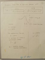
I originally thought a CLC filter was a 3rd order filter . Trying to figure out a 3rd order transfer function , in order to calculate the value of R ,
to correctly dampen the Hammond 159ZL gets a bit tricky .
However, simulating the CLC with microcaps software , fo = ( 2 * Pi * sqrt ( L * C2 )) ^ -1 and the roll off is - 40 dB per decade
so that says its a 2nd order filter .
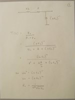
Recall , theoretically looking into a CCS , the impedance is infinite or big .
From the power supply's point of view , looking from the supply rails into the amp , many amps are effectively a CCS .
So if the power amp is effectively a CCS , looking from the power supply rails into the amp ,
the infinite impedance will have no effect on dampening the L .
The general form of a 2nd order transfer function is here .
The transfer function of the CLC filter can be figured out because sL R and (sC)^-1 form a voltage divider .
Note how C2 - the second bank of caps - affects both fo and the dampening of L .
Attachments
Last edited:
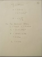
An L is missing from the algebra on page 3 . That should have read
dampening R = 2 * Zeta * L * ( L * C2 ) ^ -2
but the final equation , to plug the numbers into , to obtain the value of the dampening R , is correct .
.
.
dampening R = 2 * Zeta * L * ( L * C2 ) ^ -2
but the final equation , to plug the numbers into , to obtain the value of the dampening R , is correct .
.
.
I'm wondering about going CLC on my recently built LuDEF...
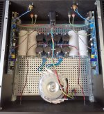
At the moment I have a single DIY audio psu with the std Antek Transformer, LT4320 active rectifiers, 3-off 0R47 Panasonic resistors per rail and motor run caps. Amp is built into a 4Ux400 case so I have space next to and just in front of the transformer to fit pair of chokes.
Im looking for advice on either of the Hammond items that are 6mH/ 0R133/ 4A (157E), or 10mH/ 0R16/ 5A. The 10mH (159ZJ) item is substantially larger and heavier, will it pick up a lot more noise than the smaller one? What's the best physical orientation with regard to the traffo?
I have 0R16 in my CRC at the moment, so am I right in thinking that the 10mH choke won't do anything to reduce the impedance?
Thanks 🙂
Attachments
The larger (10mH) choke is 0R16, smaller (6mH) one is 0R133. Would a 4A rated choke be OK on the LuDEF at 3A?
Neither is a cheap option at £75 or so
Neither is a cheap option at £75 or so
If I remember correctly, I use the Hammond 159 @ 10mH and 5 amps rating. I use two per channel (dual mono) on my Aleph J Zen. You should be safe with a pair in your LuDEF. Just ensure a bit of C after them. I am not sure about the LuDEF and CCS, but without a CCS you should ensure some good current reserves in the cap bank after the L (though of course reserves are always good!) I used overkill, 590kuF in total after the chokes. Not saying it is an example to followThe larger (10mH) choke is 0R16, smaller (6mH) one is 0R133. Would a 4A rated choke be OK on the LuDEF at 3A?
Neither is a cheap option at £75 or so
Though important not to exceed the current rating, it is also important to push enough current through chokes. Datasheets should explain min current too.
Last edited:
- Home
- Amplifiers
- Pass Labs
- CLC vs. CRC