Hello,I agree, 8 ohms is way too much for that application. The example showed what was done for a class A headphone amplifier so the resistive drop for 0.5 amps is only about 4 volts.
As to your other point, my stuff uses the most ordinary wirewounds Mouser has. Any inductance is a feature, not a bug.
No voltage drop will be much higher because ohm's law not working here.
Greetings, Eduard
Looking at the power supply schematic of the WHAMMY and the circuit board , its clear why you went down the road of adding an L .
https://www.diyaudio.com/community/threads/whammy-pass-diy-headphone-amp-guide.317803/
Because its a simple addition that would improve the noise floor of the power supply rails ( quieter than a church mouse ) .
I did have to butcher the circuit board a bit, not the end of the world. The stock transformer was replaced with a mezzanine board containing connectors for the transformer and inductors along with the rectifier/heatsink and a spot of snubbage.
But I don't quite understand because I thought those 3 pin voltage regulators chips are pretty noisy .
https://www.tnt-audio.com/clinica/regulators_noise2_e.html
Unless you left the noise generators out .
Look closer at the WHAMMY schematic: Wayne stuck 47 ohm / 220 uF filters on the supply rails to the op amp so its supply will have only nice clean DC. The output devices have no such thing but the opamp is still well within its passband for most regulator noise so junk below a MHz or so will get filtered out by feedback.
Long story short , in this application , instead of inductors , suggest looking at a 4th order LPF .
Just a 4 pole ladder filter C R C R C R C R C C .
Also , suggest simulating in the frequency domain , playing around with R values , and look at the roll off .
I like L input filters because, as mentioned before, the ground currents are much more controlled. PSUD tells me the current through the capacitors depends almost entirely on the inductor (I'll check that out) with no dependence on load, contrary to the C input filter where capacitor current is determined by the load. If that holds true then so long as your inductor values are reasonably well matched the net ground current contribution from the filter capacitors will be close to nil, whereas C input filters will have varying ground currents depending on the asymmetry of the audio signal going through the amplifier.
.
Also note what rebone has done by putting " The Beasts " as the last caps before the power amp .
Its ESR of those caps is in the ball park of 4 or 5 mOhms . So the current can get to the load ( speakers ).
So the last caps in the ladder filter should have a low ESR .
.
One could also go the McCormack route and place a medium-sized capacitor at each output device. A 15 cm (6 inch) wire has an inductance of about 150 nanoHenries, so for 4 output devices each one would see the equivalent of 600 nH, whereas a radial-leaded capacitor has an inductance of about 40-80 nH. Bypass each electrolytic with something tasty like a 10 uF X7R ceramic and your output devices will see a truly low source impedance.

I am learning new things from this thread. This is what makes diyAudio great.
I have not tried a choke input filter in any of my amps yet. So far just CLC, with the inductor bypassed by a resistor to control the Q factor. So far these have been very effective at reducing or nearly eliminating 60/120 Hz hum. I generally take care to add a film capacitor of 2.2 uF across the first C in the CLC filter, to cut higher frequency noise and absorb some of the initial ripple current.
I have not tried a choke input filter in any of my amps yet. So far just CLC, with the inductor bypassed by a resistor to control the Q factor. So far these have been very effective at reducing or nearly eliminating 60/120 Hz hum. I generally take care to add a film capacitor of 2.2 uF across the first C in the CLC filter, to cut higher frequency noise and absorb some of the initial ripple current.
Hello,
No voltage drop will be much higher because ohm's law not working here.
Greetings, Eduard
The voltage drop is composed of the inductive portion filtering out the ripple and the resistive drop caused by the inductor resistance multiplied by load current; I spoke to only the last bit.
I like L input filters because, as mentioned before, the ground currents are much more controlled. PSUD tells me the current through the capacitors depends almost entirely on the inductor (I'll check that out) with no dependence on load, contrary to the C input filter where capacitor current is determined by the load. If that holds true then so long as your inductor values are reasonably well matched the net ground current contribution from the filter capacitors will be close to nil, whereas C input filters will have varying ground currents depending on the asymmetry of the audio signal going through the amplifier.
One way of thinking about an inductor in this application that its acting as a current fly wheel . Its trying to maintain the current .
It doesn't like to see changes in current .
So if I understand your comment correctly , if the +Ve inductor tries maintain the same amount of current as the - Ve inductor
(because they are matched ) then there is very little current in the analog ground . So the analog ground is quiet .
I know with preamp power supplies , with +Ve and - Ve rails , if the ripple and noise are equal in magnitude , but opposite in phase ,
then the analog ground is quiet , because ripple and noise cancel each other out .
But ... IMO the rails need to be really well matched for this trick to work . This could also be a reason why its important to match the inductors .
So the voltage drop across them is the same .
.
Last edited:
Hello,
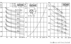
This is from a rectifier tube datasheet but it shows some crucial info.
On the left side you see the graphics when using a ten Henry choke ( of course this with tube circuits)
At the start of the line you see what is happening when there is no resistor taking care of a minimum current flow. With more than 10 H the rise of the voltage on the first cap wont go up that high.
Of course you need your circuit to work in the " area " where the line is kind of flat.
TAKE A LOOK AT THE RIGHT GRAPHIC WHICH IS WITH CAPACITOR INPUT.
The dcr of the choke with a circuit that takes serious current is important. But it is not that important if the current is kind of steady.
The French made a preamp with a two bobbin choke with one bobbin in the plus and the other in the negative side. I have written about it elsewhere.
You could do the same with the Lundahl chokes because they have two 100% identical coils. I never tried but if i remember correctly Lundahl told me back then the current should be identical in order to make it work.
95 % of my chokes are used in single rail supplies and people who use them in " double rail supplies" all use two separate chokes. Like the ll2771 in a Hiraga 20 watt poweramp clc with a 2,5 or 2,75A current rating.
Of course with single rail you can use the choke also in a different connection, look at the lundahl datasheets.
Greetings,Eduard
Attachments
I am learning new things from this thread. This is what makes diyAudio great.
I have not tried a choke input filter in any of my amps yet. So far just CLC, with the inductor bypassed by a resistor to control the Q factor. So far these have been very effective at reducing or nearly eliminating 60/120 Hz hum. I generally take care to add a film capacitor of 2.2 uF across the first C in the CLC filter, to cut higher frequency noise and absorb some of the initial ripple current.
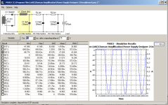
I cannot emphasize this strongly enough: PSUD is your friend. It does only one thing, but it does that one thing extraordinarily well.
Choke input filters are IMO wonderful for class A amplifiers and other places with essentially steady current draw such as preamplifiers. They are not, repeat not, recommended for class AB amplifiers since you'd need an unwieldy set of inductors to keep the output voltage steady and also to keep from smoking the rectifiers because of flyback voltage when the current collapses to zero in the chokes.
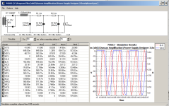
Here is the rectifier voltage with a choke properly specified for the current draw, followed by the rectifier voltage with a choke too small for the job.
Attachments

Check out the Hammond 196Q2. A dual coil choke that can have the coils wired in series or parallel, as indicated in the datasheet.
Individual coils appear to be 20 mH @ 2 Amps, with 0.24 Ohms DC resistance in each coil.
Individual coils appear to be 20 mH @ 2 Amps, with 0.24 Ohms DC resistance in each coil.
Hello,
Using the ll2771 will allow you to use a transformer with a smaller current rating.
When used for choke input get the airgap adjusted to the current you need and gain some extra mH
I have a few in use.. One as 3H 1A ( series connection) but others with 100mA rating but also used in parallel and airgap adjusted for 2,5A
Greetings,Eduard
P.s better go for more mH
Attachments
Hammond high current chokes offer a wide range of settings, but they are only marginally cheaper than Lundahl, at least in Europe.
Am I right saying that a good cost/performance solution would be to build a mono bipolar PSU with chokes tailored for both channels bias current?
If so, the LL2773 / 3.5A offers 95 mH and 0.44 Ohm for 3.5A with coils in serie. One transformer with two secondaries, two chokes, and the usual bunch'o'caps...
Considerable cost and footprint, but suitable for almost every firstwatt/babblefish class A babies.
It may even be possible to arrange the coils for better common mode rejection, but Lundahl's typical schematic use a cap before the choke, maybe it's not mandatory?
Hello,
The Lundahl chokes are far better constructed, are constructed in a way similar to their signal transformers offer better filtering.
In one of my tube build they worked better than the Tango choke model designed for choke input. I have used different Lundahls for choke input some up to 2,5A .
Like i wrote before check the current rating you need and get the biggest number of mH especially benificial for choke input.
The LL 2733 is 400mH at 1,7A so at 3,5A it will be a little under 200mH with adjusted airgap. I have a friend who uses this choke in common mode figuration for a single rail choke input supply for a class A power amp. So probably can be done to put the two coils in series
Of course if you make two mono units you will have double the number of mH.
Or use the much bigger LL 2771 with the two coils in parallel 5,6/2 is 2,8 ohm. That one is 700mH at 2A .
The difference in sound between let us say 200mH and 700mH is BIG.
4 LL2771 won't be cheap ( there were 3 on Ebay in France) but they will work forever. I think the company in Estonia will offer free shipping about 500 € so that will be an advantage because they are 4,9 kilogram each.
I have 4 items with LL 2771 in choke input configuration and two of them used the LL 2733 before the bigger one was available.
Greetings Eduard
P.s ALWAYS use a resistor across the first cap to assure the minimum current.
My point was to limit the cost by using only 1 pair of chokes for 2 channels, so each choke has to be able to deliver 3 to 4A (3.5A is fine, almost every class A amps from the forum can be biased with 24v/1.75A).
But I get your point.
Buying only two chokes may help to get more expensive ones, with more mH.
I don't know what's the acceptable resistance for a class A PSU, I was wondering below 0.5 Ohm. Maybe there's more to gain from higher inductance than lower resistance (to some extent?).
But I get your point.
Buying only two chokes may help to get more expensive ones, with more mH.
I don't know what's the acceptable resistance for a class A PSU, I was wondering below 0.5 Ohm. Maybe there's more to gain from higher inductance than lower resistance (to some extent?).
Hello,
Then i would SURELY go for pair of LL 2771 with airgap adjusted so it can take 4A with coils in parallel so you will get a 350 mH choke. With 3,5A you will get a little extra mH but better to have some margin.
With the LL 2771 each mH is much cheaper than with the other chokes.
My friend uses LL2771 in clc supply for hiraga 20 watt stereo amp. Adjusted current rating to 2,50A coils in parallel so 2,8 ohm. No problem ,,!!
Greetings Eduard
Do you have a rule of thumb for guessing how much current has to be drawn to avoid voltage to rise (= ensuring a true choke input)?
1/10 of 4A is still quite a lot, maybe 1/20 (120R at 24V)?
1/10 of 4A is still quite a lot, maybe 1/20 (120R at 24V)?
Hello,
There is a formula.
If dc voltage at the first cap is 24 volts and the input choke is 0,4 Henry the minimum current then needs to be
24/0,4= 60 mA
Of course you will still have some extra voltage drop across the choke when the circuit also draws its current .
But with only the resistor across the first choke your dc voltage at the first with 28 volt transformer should be something like 25 volts. If it is higher you dont make it work like a choke input. Yes, the circuit will take current right away probably but better be safe than sorry. You will be able to use 40 volt caps for a 25 volts supply because the biggest part of the voltage drop will be there because is works as a choke input with just the resistor pulling the minimum current.
There is also some theory that the current taken by the resistor should only be a small part of the total current( circuit plus resistor ). If the total current is 3 A or more 60 mA is nice.
With the LL 2771 with two coils in parallel is 2,8 ohm and 3 or 3,5 A current you will have s considerable voltage drop . Could well be you need a 36 volts ac transformer .
The LL 2733 with coils in parallel will have lower dcr but these you would need 4 and then you get 200mH 1,7A at 0,85 ohm. You can simulate if 350mH from the ll2771 at 2,80ohm will be better.
You should not worry to much about dcr.
Greetings Eduard
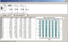
Or you could bring up a PSUD simulation and make sure the choke current stays above zero at the minimum load. The first example uses a choke properly sized for the current draw while the second is too small, with the red trace in both examples being choke current and the other trace diode voltage. Note how the diode gets zapped when the choke current drops to zero.
Attachments
Hello,
Most of my gear is tube gear so i dont care to much about dcr of chokes
I have one class D amplifier in my 2.1 " movie set up) If i remember right the maximum current there was around 600 mA . It has a choke input supply with the LL2771. If i remember right it has a " standard" airgap so it will be 3H at 1 A. Two coils of 5,6 ohm in series.
I have a dddac same 3H but it has shunt supply so current should be " rocksteady "
I know the ll2771 works very well in a Hiraga 20 watt clc supply with coils in parallel
The ll2733 works well as choke input in a mono class A design with about 1A running wired in common mode if i remember well so 2x 1,7 ohm.
Suppose we have a class A power amp that needs a choke input power supply. We could make one big power supply or two mono blocks
There are some choices to be made which one would theoretically be the best? Some specs have been changed a little bit for easier comparisons. Current taken by one channel 1,5A
Two monoblocks so each two chokes 200mH 1,7 A rating dcr 0,85 ohm
One stereo amp with 2 chokes and shared supply for both channels. For this one we would use LL2771 which will be more than 400 mA at 3,4 A but dcr 2,8 ohm and of course double the current being drawn
Using the ll2771 in a double mono will give you a little more than 1000mH at 1,5 A and 2,8 ohm
Of course one could use two ll2733 for a stereo amp but that is just 100mH which would require some serious current going through a resistor.
Could it be that two monoblocks with each two ll2733 will outperform one stereo amp with two ll2771?
Monoblocks will probably allow you easier wiring layout to the circuit boards .
Greetings,Eduard
P.s these chokes will not age like capacitors will do
Hello,
Once you know the choke you will be using calculate the minimum current needed, at a little extra if you like, get the right resistor across the first cap and make it stay there.
This is a crucial element in a choke input supply
Greetings,Eduard
P.s just saw a power supply choke made for 800 cps ( airforce or navy) on ebay . You want to try that one at 100 or 120 cps? )
Last edited:
- Home
- Amplifiers
- Pass Labs
- CLC vs. CRC