
Dear all,
In any thread where an amp is being developed with community effort, it is necessary to keep all mods suggested and implemented. So, it is requested to keep all modified diagrams to be retained than REPLACED in the first post. Those that come later will lose the context and continuity. Also, it may be better to post the modified diagram in the current post also to avoid going back to post 1 just to see the diagram and come back to see the comments.
my 2p.
gannaji.
I added 1N4148, but I will add BAV21 instead.BAV21 is faster, but 1n914 or 1n4148 will also do.
BAV21 is widely available.
They say it is lower capacitance.
Why not add latest schematic on both first post and later in the thread.Dear all,
In any thread where an amp is being developed with community effort, it is necessary to keep all mods suggested and implemented. So, it is requested to keep all modified diagrams to be retained than REPLACED in the first post. Those that come later will lose the context and continuity. Also, it may be better to post the modified diagram in the current post also to avoid going back to post 1 just to see the diagram and come back to see the comments.
my 2p.
gannaji.
To have it later in the thread people will have to scroll back to the schematic.
Some info on why an output coupling inductor is important in feedback amplifiers:-
https://hifisonix.com/wp-content/uploads/2014/11/Output-L_1.pdf
Re the 2uF capacitive load, this is generally accepted as the worst case load you are likely to see with an electrostatic speaker. However, as the doc above shows, it takes only a small amount of L (0.5 to 1uH) to ensure an amp can drive any practical capacitive load, assuming it’s compensated correctly in the first place.
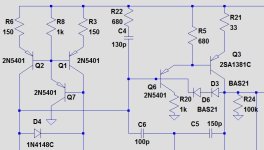
Re the Baker clamp diode, if you can handle small SMD devices, the Vishay and Nexperia BAS21J have the lowest diode reverse bias capacitance specified at IIRC 1.2 pF worst case. That said, I’ve used BAV21 with good results as well.
I like it if thread #1 has summary and links to different important schema, layouts and mods etc. Readers can keep #1 in a tab and the links opened in new tabs. I really like the D-Noizator thread in this regard,Why not add latest schematic on both first post and later in the thread.
To have it later in the thread people will have to scroll back to the schematic.
As long as the insulation L is attached, resonance is unavoidable with capacitive loads, but I think it is possible to reduce its effect. Try the following:But is it possible to get away with the resonance at T?
The standard value for R in parallel with L used to be around 10Ω, but recently 4.7 to 2.2Ω is often seen. This dampens the Q of the resonance.
Place the zobel after the inductor as well. (Example: 22Ω + 0.047uF)
This does not reduce Q, but isolation L of 5uH may be a little large. 1uH or less (~0.5uH) may be sufficient.
I think it is generally about 1/10 of the maximum collector current, but even if it does not lead to destruction, overdriving the VAS may cause other problems. My previous post may be helpful. The context of this post should be read from #1313.What do you consider a safe limit for base current on a 2SA1209 for example? Datasheet does not specify it.
Does it have to be BAV21 or can one use some other diode?
One thing "better" means in this case is low capacitance.
As I mentioned in my previous post, the interelectrode capacitance of Baker clamp diodes leads to worsening of high-frequency distortion. As mlloid and minekk say, it is better to choose one with a small capacity.I see BAV21 used as VAS baker clamp in most of cases.
However, in my experience, the three candidates in my previous post have a decreasing distortion penalty from left to right.
In any case, changes are easy and without cost to make in simulation😀. It's a good idea to try out different things.
P.S
Oh, Bonsai already posted something similar.
Last edited:
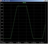
Just to talk about recovery from overdrive, because it is an important issue in amplifiers, and especially those with feedback. When an amp is driven into clipping, it is effectively running open loop and the LTP or diamond buffer will then drive the second stage open loop and this generally means the front end will have switched, and all of the available front end signal current will be getting pumped into the VAS/TIS. And this is what causes rail sticking. There are two problems with this. The first is it generates a lot of HF harmonics that make things sound worse, but also pose a serious threat to the tweeters. The second is that the amp can break into HF oscillation as it exits clipping - which only happens because the input signal will have moved well away from overdrive.
In bad cases, rail sticking can be as much as 3-5us. So, the upshot of this is, I would recommend you always check how your amp behaves on overdrive. I happily trade a few ppm in HF distortion for clean overdrive recovery since there is very little HF energy above 10 kHz anyway - I do not know of any music modern or otherwise that demands full output from an amp at > 10kHz.
https://hifisonix.com/wp-content/uploads/2019/02/Anti-Saturation-Diodes.pdf
That's right.I happily trade a few ppm in HF distortion for clean overdrive recovery
I also design with low distortion as a target, but I believe that I can only be proud of it if it is stable and safe.
H
HAYK
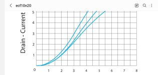
Mistrust the spice model of 10n20 and probably its Co.
I measured the model for 10v Vds the Id current for 1, 1.5, 2, 2.5,and 3 Vgs.
The 1v and 1.5v are correct but with 2v I get 1.18A instead of 1.35A. With 2v, instead of 2A I get 1.75A. With 3v, instead of 3A I get 2.38A. As if the modler used the 25°C curve for the first two and 75°C for the last 2 and interpolated for linear progression.
The low distortion on simulator is very far from the reality.
Attachments
@HAYK
What models should I use?
I use the models here:
What models should I use?
I use the models here:
.SUBCKT ECX10N20 1 2 3
**********************************************
* Model Generated by PEDC *
Copyright(c) Power Electronics Design Centre
**********************************************
- All Rights Reserved *
- Power Electronics Design Centre *
- Dept of Elec & Electronic Engineering *
- University of Wales Swansea *
- Singleton Park *
- Swansea SA2 8PP *
- Tel : +44 (0)1792 295420 *
- Fax : +44 (0)1792 295686 *
- E-mail : pedc@swansea.ac.uk *
* Model generated on Dec 6 1999
Last edited:
Hi. IMHO it's better this way.How can I make my amplifier overdrive safe?
Attachments
Thanks @printnik
How about ECX10N20/ECX10P20 gate capacitances.
Rod Elliott say amplifier can be unstable with these transistors.
https://sound-au.com/project101.htm
I am thinking of using different gate stoppers for the two transistors.
220 Ohm for ECX10N20
150 Ohm for ECX10P20
Anyone have any experience with these MOSFETs?
Last edited:
ThanksBest known models are inside "Hegglun-Lateral-models2.txt"
I will see if I can use them models.
@HAYK: There is no reason to mistrust the model in that aspect. Please keep in mind that the model is based on a TYPICAL MOSFET transfer curve. The data sheet grants a range of gate threshold voltage. So you cannot expect exact bias calculations from any model. Another aspect is that using two transistors of same type, for instance the differential amplifier, are modelled exactly the same. Which in reality does not occur and results in too optimistic results. Not the fault of any models, but the fault of the user with wrong expectations.
Last edited:
- Home
- Amplifiers
- Solid State
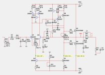
- Cello One. Good Amplifier 15 Watt with TMC and Laterals