hello
I decided to build an amplifier from this topic
Why ?
Because I really liked the cooperation of the form members and the topic itself is very educational.
I learned a lot about OLG
;-)
My PCB design is a thank you for your work
My PCB design is based on the almost latest version of the schematic i.e. from post #401
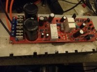
The entire PCB design is adapted to the elements I have at home and to the housing I have. It is a small aluminum housing with heat sinks on the sides. The heat sink measures approximately 200x60mm. which forced the PCB to be quite long and narrow
I modified the diagram itself a bit - I used 2SK1058 / 2SJ162 Hitachi (I have it in stock), I added source resistors and pins for measuring current. Regulation is much simpler.
I also added a trimmer for offset regulation.
I also placed a power supply with separate discrete rectifiers for each power supply branch and large filter capacitors on the PCB.
I also added delayed speaker switching and DC-protect (powered from a separate 9V transformer)
Speakers are expensive devices and I think it's better to spend a few euros more on security
I have already launched the first channel. Assembled from proven, measured elements, I managed to start it without any problems. No smoke, no booom ;-)
Offset and quiescent current are stable and adjustable without any problems ( offest about 0.1mV , quiescent current 200mA)
The amplifier was tested with an dummy load of 8Ohm+100nF
Square wave 20Khz 10Khz 1Khz without any problems
I will add an oscilloscope screenshot later
Quickly - a few songs on the loudspeaker in mono - it promises to be interesting...
The protections work - the speaker turns on after about 2s. DC protect works above +/-0.7V
For now, I have to stop working for a week or more
When I find time, I will finish the second channel and put everything in the housing
Then - further measurements and listenig test ( in stereo )
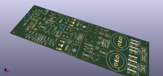
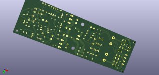
The photos are the top and bottom from KiCad and the finished amplifier on the test heatsink
As you can see - there are large spaces for capacitors - I plan to launch a version with a higher supply voltage (+/-30 V)
Thank you once again to everyone who helped design this amplifier
I decided to build an amplifier from this topic
Why ?
Because I really liked the cooperation of the form members and the topic itself is very educational.
I learned a lot about OLG
;-)
My PCB design is a thank you for your work
My PCB design is based on the almost latest version of the schematic i.e. from post #401
The entire PCB design is adapted to the elements I have at home and to the housing I have. It is a small aluminum housing with heat sinks on the sides. The heat sink measures approximately 200x60mm. which forced the PCB to be quite long and narrow
I modified the diagram itself a bit - I used 2SK1058 / 2SJ162 Hitachi (I have it in stock), I added source resistors and pins for measuring current. Regulation is much simpler.
I also added a trimmer for offset regulation.
I also placed a power supply with separate discrete rectifiers for each power supply branch and large filter capacitors on the PCB.
I also added delayed speaker switching and DC-protect (powered from a separate 9V transformer)
Speakers are expensive devices and I think it's better to spend a few euros more on security
I have already launched the first channel. Assembled from proven, measured elements, I managed to start it without any problems. No smoke, no booom ;-)
Offset and quiescent current are stable and adjustable without any problems ( offest about 0.1mV , quiescent current 200mA)
The amplifier was tested with an dummy load of 8Ohm+100nF
Square wave 20Khz 10Khz 1Khz without any problems
I will add an oscilloscope screenshot later
Quickly - a few songs on the loudspeaker in mono - it promises to be interesting...
The protections work - the speaker turns on after about 2s. DC protect works above +/-0.7V
For now, I have to stop working for a week or more
When I find time, I will finish the second channel and put everything in the housing
Then - further measurements and listenig test ( in stereo )
The photos are the top and bottom from KiCad and the finished amplifier on the test heatsink
As you can see - there are large spaces for capacitors - I plan to launch a version with a higher supply voltage (+/-30 V)
Thank you once again to everyone who helped design this amplifier
Attachments

@lineupExcellent.
Any component power ratings in particular to watch out for?
Are all the resistors 1/4w?
What power ratings should be used for R17, R18, R5, R6?
I made an SMD version of this circuit. It played briefly before some of the smoke escaped...... 😤
The amp still plays, but lower volume and the channels are out of phase.
Suspecting R18 is the culprit as one channel is open circuit and the other looks discoloured but measures in the ballpark.
I notice Zoltan has used some 5W ceramic resistors. I used 2W for R17 and placed it inside an air-core inductor as I've done on previous builds.
avtech
I added source resistors and pins for measuring current. Regulation is much simpler.
I have ceramic 5W 0.1 Ohm in stock The resistor in Zobel is 3W, in the feedback is 1W, in the power supply branch (22 Ohm) is 2W. The rest is standard 1/4W
I added source resistors and pins for measuring current. Regulation is much simpler.
I have ceramic 5W 0.1 Ohm in stock The resistor in Zobel is 3W, in the feedback is 1W, in the power supply branch (22 Ohm) is 2W. The rest is standard 1/4W
I see. The source resistors are a good idea.
When you say "in the feedback", do you mean the 22k?
When you say "in the feedback", do you mean the 22k?
Finally got this one sorted. Had a tiny whisker that was shorting the source of a mosfet to the heatsink (and therefore ground).
So here is my SMD version so far:

3D printed fixture for the solder paste mask:

Ready to bake:

First prototype board populated (65mmx100mm, stereo):

First proper power up test after setting bias:

I went with the 5551 transistors rather than the very expensive all-in-one package.
2SK2221 and 2SJ352 were what I have to hand.
3.6uH air-core inductors were about the max that I could wind in the space I'd allowed.
My standard 2k2/220p input filtering. 3.3uF input capacitor.
24/-24 SMPS with 10A CLC filtering. (the board is running at +/-24v and 180mA bias).
I haven't run any empirical tests yet, but the amp sounds very nice so far.
Totally silent with no input and volume cranked to the max.
I need to make a couple of changes to the layout to fix up some orphans that happened during board revisions, but there were no major problems.
Got some work ahead to finish the enclosure, but have a nice design in mind.
This was my first proper SMD layout and the first time I have used a reflow oven to bake a board.
It went surprisingly well once I re-flashed the oven's firmware, added a cold junction and calibrated the thermocouples properly.
So here is my SMD version so far:
3D printed fixture for the solder paste mask:
Ready to bake:
First prototype board populated (65mmx100mm, stereo):
First proper power up test after setting bias:
I went with the 5551 transistors rather than the very expensive all-in-one package.
2SK2221 and 2SJ352 were what I have to hand.
3.6uH air-core inductors were about the max that I could wind in the space I'd allowed.
My standard 2k2/220p input filtering. 3.3uF input capacitor.
24/-24 SMPS with 10A CLC filtering. (the board is running at +/-24v and 180mA bias).
I haven't run any empirical tests yet, but the amp sounds very nice so far.
Totally silent with no input and volume cranked to the max.
I need to make a couple of changes to the layout to fix up some orphans that happened during board revisions, but there were no major problems.
Got some work ahead to finish the enclosure, but have a nice design in mind.
This was my first proper SMD layout and the first time I have used a reflow oven to bake a board.
It went surprisingly well once I re-flashed the oven's firmware, added a cold junction and calibrated the thermocouples properly.
The zobel resistor R17 should be 5 Watt or maybe 2 Watt will do.@lineup
What power ratings should be used for R17, R18, R5, R6?
I made an SMD version of this circuit. It played briefly before some of the smoke escaped...... 😤
The amp still plays, but lower volume and the channels are out of phase.
Suspecting R18 is the culprit as one channel is open circuit and the other looks discoloured but measures in the ballpark.
I notice Zoltan has used some 5W ceramic resistors. I used 2W for R17 and placed it inside an air-core inductor as I've done on previous builds.
R18 can be 2 Watt.
All other resistors can be low power. Say 0.6W or 0.5W.
Nice job you have done.
I am very pleased it worked out well and with good sound.
To all interested in CELLO ONE circuit
you find it in first post#1 of this topic.
you find it in first post#1 of this topic.
- Home
- Amplifiers
- Solid State
- Cello One. Good Amplifier 15 Watt with TMC and Laterals