diagram #388 by Lineup
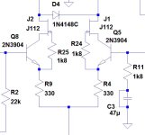
Hi. For better stability of increasing the phase margin, it is better to put degrading resistors in a differential cascade of 200-330 ohms. Additional field-effect transistors will increase the phase margin by 23 degrees and reduce distortion.
Attachments

200 ohm still sounds acceptable, but remember you are increasing noise at the same time. I would not use higher resistance values, rather 100 ohm.
200 ohm still sounds acceptable, but remember you are increasing noise at the same time. I would not use higher resistance values, rather 100 ohm.
I compared the noises by adding a directive
.noise V(OUT) V4 oct 100 20 20k
The noise difference is 2dB (-118 -120dB). Even if you listen with headphones connected via a current limiting resistor, you will not hear the difference between - 100 dB and -98 dB.
Hi
I am curious about the removal of the ground loop resistor.
I've seen many power amp pcb's that did not have this, and all hummed
when not build as mono blocks.
The idea is to split the power ground from the signal ground.
The decoupling caps, and probably anything drawing DC current, should
connect to power ground.
The feedback and the input resistors/caps should be on the signal ground.
I've played with this before, and found that if only one of the channels was connected to
the preamp, there was no hum. But as soon as both channels are connected, I got hum.
(Could this be a preamplifier problem?)
Looking at different schematics here on the forum, most, if not all, have it.
I would not leave it out.
When getting to the pcb creation, one can make room for the ground loop resistor,
and then use a jumper if preferred.
I for my part haven't noticed any negative implication to the sound.
Keep in mind that your simulator doesn't show everything, this being one of them.
I would add that even Rod Elliott added a hum breaking resistor to his P101. I mention this because he is extremely picky about adding extra components, and nearly always favoring simplicity unless there is a substantial gain to be had form an added part. He also adds a 100nf bypass cap.
The cap makes sense. Some also use two diodes (1n4148) in parallel to the ground resistor, to "catch" startup dc peaks I guess. In most cases however I think that is not needed. Fx using a 4.7 ohms resistor with diodes in parallel, there would be a DC current of about 127mA before the diodes start to conduct, in which case I would probably think something is wrong to beging with.
No, it is the simplest issue of essential physics - wiring issue of signal ground loops. For this reason, two separate power supplies for 2 channels are best, or at least separate secondary windings of the PSU transformer.I've played with this before, and found that if only one of the channels was connected to
the preamp, there was no hum. But as soon as both channels are connected, I got hum.
(Could this be a preamplifier problem?)
The inter-ground “hum-reducing” resistor is a tricky solution. It may help in case of faulty groundloop setup, however it worsens best-achievable S/N and in case of fault (burnt by ground current due to some error) it may destroy the amp - I have seen It several times. Inter ground resistor is only a band aid, not a real solution.
here is a typical layout: https://www.diyaudio.com/community/attachments/screenshot-2022-09-15-204306-jpg.1091004/
looks nice, but the separation of the two amp boards also separates the input wiring = big loop area
looks nice, but the separation of the two amp boards also separates the input wiring = big loop area
User Bonsai’s document on grounding covers this well. He describes visual what the issue is and ways to mitigate it. It’s an excellent read. You can find it on his site
One of the biggest takeaways for me is keeping the inputs jacks right next to each to connect the grounds and shunt with a cap. Most of us want to have the inputs on the right and left by the amp boards for the visual symmetry on the back panel. Looks nice and neat, but can lead to enlarged loop area problems.
Post #388 has the final schematic:
https://www.diyaudio.com/community/...att-with-tmc-and-laterals.406282/post-7539229
There will be no more work on this 🙂
https://www.diyaudio.com/community/...att-with-tmc-and-laterals.406282/post-7539229
There will be no more work on this 🙂
Excellent.
Any component power ratings in particular to watch out for?
Are all the resistors 1/4w?
Any component power ratings in particular to watch out for?
Are all the resistors 1/4w?
Doesnt look nice at all on an electrical POV, the mistakes can be spoted as easily as an elephant in a corridor.here is a typical layout: https://www.diyaudio.com/community/attachments/screenshot-2022-09-15-204306-jpg.1091004/
looks nice, but the separation of the two amp boards also separates the input wiring = big loop area
Was looking into parts on this one.
The SSM2212RZ are currently ~$15AUD each.
Bearing in mind that I can get 200x 5551s for the same price as one of those matched packages, is it really worth using them or better to just stick to the 5551?
The SSM2212RZ are currently ~$15AUD each.
Bearing in mind that I can get 200x 5551s for the same price as one of those matched packages, is it really worth using them or better to just stick to the 5551?
Lineup sir you build great designs.Cello One
All data comes from SPICE simulation.
I leave building this amplifier to diyAudio members.
I can not build it.
Max 15 Watt into 8 Ohm Class AB
TMC compensation
THD 0.00005% at 1 Watt
Easy to find components are used
View attachment 1243957
I like it very much.
i wanna be your student😀
- Home
- Amplifiers
- Solid State
- Cello One. Good Amplifier 15 Watt with TMC and Laterals