With Hitachi latFETs I had similar results.Thanks @printnik
How about ECX10N20/ECX10P20 gate capacitances.
Rod Elliott say amplifier can be unstable with these transistors.
https://sound-au.com/project101.htm
I am thinking of using different gate stoppers for the two transistors.
220 Ohm for ECX10N20
150 Ohm for ECX10P20
Anyone have any experience with these MOSFETs?
See this post for the details:
https://www.diyaudio.com/community/threads/latfet-amp-based-on-philips-ah578.367494/post-6525699
The role of caps on GS is to equalize input capacitance on both devices (P and N).
Usually N device has lower capacitance than P device, so some designers ADD extra cap on N device to make them equal.
Example: Rod Elliot's P101.
If capacitances are not equal - that may cause oscillations.
Another way of dealing with this issue, is by using DIFFERENT gate stoppers, using formula RC = constant, where R is gate stopper resistor, and C is input capacitance of the FET. Adjust R on the both devices, so RC value are equal on upper and lower FETs.
Example:
Let's say the 2SJ162 has a gate stopper of 100 Ohm and a gate
capacitance of 900pF, the RC time constant is just Rgate x Cgate=RC time constant,
so 100 x 900x10^-12=90nS. If we want 'balance' we need a resistance on the gate of
the 2SK1058 that gives the same time constant.
So, Rgate x 600pF = 90nS, solve for Rgate. In this case Rgate needs to be 150 Ohm.
Exicon double die devices: P/N have different capacitance, N device has 900pF LESS input capacitance (I actually measured
it to confirm the datasheet) so in this amp, upper Rg=470 Ohm, and lower Rg = 220 Ohm.
For single die Exicons I checked their datasheets, and their Ciss (Cgate) are equal (500pF), so gate stoppers SHOULD be the same (equal).
Last edited:
I'm thinking that has to be a typo in the datasheet, I'm not sure how both N & P channel would have exactly the same Ciss values. In the Hitachi mosfet databook all the P channel Ciss values were always higher than the N channel.For single die Exicons I checked their datasheets, and their Ciss (Cgate) are equal (500pF)
I performed some simulations in Ltspice using Ian Hegglun's Exicon models and using the same gate resistor values the frequency rolloff was different. I ended up using 220R for the P channel and 470R for the N channel, this seems to correspond (more or less) with the equivalent Hitachi versions.
I wonder if anyone has actually measured the Ciss values in the single die versions ?
I agree, I always heard that Exicons are using exactly same die/process as was used for original Hitachis, which didn't have equal Ciss..
And double-die Exicons have different Ciss...
I only have double-die fets in stock, so can't help with measuring single-die ones...
And the only signle-die fets I used in the past were original Hitachis, so I was using un-equal gate stoppers.
And double-die Exicons have different Ciss...
I only have double-die fets in stock, so can't help with measuring single-die ones...
And the only signle-die fets I used in the past were original Hitachis, so I was using un-equal gate stoppers.
BUT Elliott used a cap GS on the ECX10N20 to equalize those mosfets.For single die Exicons I checked their datasheets, and their Ciss (Cgate) are equal (500pF), so gate stoppers SHOULD be the same (equal).
And I have read in forum that 10N20 has 650pF and 10P20 has 1100pF at certain level.
I will search and see if I can find that thread again.
We should take the datasheet not for the truth regarding Ciss 500pF on both.
Here is the post with measurment of capacitance for ECX10N20 and ECX10P20
https://www.diyaudio.com/community/threads/sound-of-zenquito.35782/post-6448661
https://www.diyaudio.com/community/threads/sound-of-zenquito.35782/post-6448661
Why not add latest schematic on both first post and later in the thread.
To have it later in the thread people will have to scroll back to the schematic.
Adding makes sense, but replacing doesn't let us see the evolution and what some posts refer to. Does the first post no longer contain the original schematic?
Some time ago in another thread I posted a sim of OPA552 with ECW20N20 and ECW20P20. It was simmed by others and they noticed the ucap models of these fets were too optimistic. Not inclined to set up elaborate measurements, I tried to sort out "what matters" in a sim comparing darlington and mosfet, with input impedance (R62,63) as parameter. The results were quite telling.Here is the post with measurment of capacitance for ECX10N20 and ECX10P20
https://www.diyaudio.com/community/threads/sound-of-zenquito.35782/post-6448661
H
HAYK
I have 2 models of ecf10n20, the first is labeled 10n20-70c. C maybe Cordell. It comes from Maplin circuit. The second is a file I found on minek's lib. Ltspice doesn't read but can be made auto-generated, this one is a true ideal to get 0% THD.
Attachments
No. first post has the latest published circuitAdding makes sense, but replacing doesn't let us see the evolution and what some posts refer to. Does the first post no longer contain the original schematic?
That makes sense.I'm thinking that has to be a typo in the datasheet, I'm not sure how both N & P channel would have exactly the same Ciss values. In the Hitachi mosfet databook all the P channel Ciss values were always higher than the N channel.
I performed some simulations in Ltspice using Ian Hegglun's Exicon models and using the same gate resistor values the frequency rolloff was different. I ended up using 220R for the P channel and 470R for the N channel, this seems to correspond (more or less) with the equivalent Hitachi versions.
I wonder if anyone has actually measured the Ciss values in the single die versions ?
ECX10P20 is said to have 1100pF in operation and ECX10N20 roughly half = 650pF.
See the link I posted: https://www.diyaudio.com/community/threads/sound-of-zenquito.35782/post-6448661
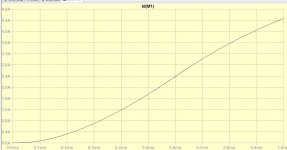
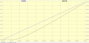
One of the best examples of the difference between ECW-N and ECW-P was observed in my study for low IMD: series resistor with gate has to be different. BTW the amp clips well and is fairly well protected against input overload. A more "realistic" distortion results when increasing the gain. Notice the value of the series R in the P-device.
When using same value as in N device, the virtual ground node looks different.


When using same value as in N device, the virtual ground node looks different.
I see you use emitter resistors 0.22 Ohm in the output. This will not be necessary ... or?
No, source resistors are not necessary
Source resistors should not be needed with a single pair of Lateral MOSFET output devices. However, adding them does make setting the bias easier. Maybe a provision for optional 0.1Ω resistors?
Thanks @AridaceOne of the best examples of the difference between ECW-N and ECW-P was observed in my study for low IMD: series resistor with gate has to be different. BTW the amp clips well and is fairly well protected against input overload. A more "realistic" distortion results when increasing the gain. Notice the value of the series R in the P-device.
When using same value as in N device, the virtual ground node looks different.
View attachment 1244412
View attachment 1244411
Here is the current circuit.
I have done numerous changes:
Input filter now has 82pF cap
Moved the DC-offset adjustment to the top at the current mirror
Changed emitter resistors in the mirror
Added baker clamp diode
Added overcurrent protection
Added mosfet protection zener diodes
Changed gate resistor values
Output inductor is now 6uH
Increased current in the input LTP
I have 2sk1058,j162,i have Exicons single and double die too.
I can measure all them for static cap if it is useful.
I can measure all them for static cap if it is useful.
- Home
- Amplifiers
- Solid State
- Cello One. Good Amplifier 15 Watt with TMC and Laterals