This looks incredibly good. How good are the lateral Mosfet models, aren’t they only simplified versions?
https://www.diyaudio.com/community/...f08n20v-alf08p20v-alf16n20w-alf16p20w.241619/
https://www.diyaudio.com/community/...f08n20v-alf08p20v-alf16n20w-alf16p20w.241619/
Lineup, please permit me to pass a few comments on what is potentially a great little amplifier - it looks simple and could be a foolproof design.
1. Test the amplifier recovery time by feeding it with a 5-10 kHz sine wave with 10-20% overdrive. Does the amplifier recover quickly (<1us) without rail sticking or any oscillations?
2. Do a loop gain plot with various capacitive and resistive loads on the output, making sure the loop gain and phase margins are adequate to ensure there is no possibility of instability. A worst-case test regime would be 2uF//2 Ohms, but you should in any event test over a wide range to get a feel for the stability envelope. Use the '.step param or equivalent directive in your simulator to do this.
3. Your rise/fall times are too fast. Very fast rise/fall time capability almost always translates into ringing and potential instability issues - be they loop gain/phase related, or by triggering parasitic oscillation. For an audio amplifier, 2-3us rise fall/time is where you want to be. Some highly rated amplifiers feature >5 us rise fall times
4. You have no bandwidth-limiting filter on the front end. You should include that for RFI.
5. You are running the LTP at 9.5mA per side which is very high. It would be better to run it at 5mA per side and increase the LTP emitter degen resistors to 100 Ohms per side. This will reduce the bias current errors and make no difference to the performance provided you then address the compensation network (R12, C3, C5) per below
6. I don't think the compensation is behaving like a TMC network should because of the values you have used. Put the amp back to Miller come (remove R12 and C3). Adjust C5 for a ULGF of 2-3 MHz. Put C3 back in at 2 x the value of C5. Set R12 to 2-3k Ohms. You may have to trim C5 up in value and also C3 because the ULGF will go up (C3 and C5 are in series). But, just make sure the loop is closed again at c. 2-3 MHz. When you look at the loop gain plot, you should get a flat response 10-20 kHz, then it slopes off at 40 dB/dec before reverting back to 20 dB/dec (typically around 500-1MHz) and then crossing the ULGF at 2-3 MHz
7. For square wave testing, use c. 2 V pk~pk 3-5 kHz and check for overshoot/ringing into a purely resistive load. Don't use very high square wave amplitudes because what you are looking to study in this test is the loop gain performance without large signal parasitic effects. When the output (especially with mosfets) and VAS voltages swing close to the rails, there are changes in Cob, mosfet input capacitance etc that can confound the loop stability analysis. Those are separate issues that must be treated as parasitic, or secondary issues.
8. Do not be blinded by ultra-low THD. You can get ultra-low THD and have plenty of problems in 1-7 above. What you want is a stable amplifier that can drive any load thrown at it and recover quickly and gracefully from overdrive i.e. clipping and have low IMD (means better than -90 dBr at full power). Anything below 0.005% at full power at 20 kHz but meets all of the criteria I just mentioned above classifies the amplifier as high performance.
Anyway, hope this helps 🙂
Last edited:

@TO: If you want to share your design I would expect you to share your simulation file as well instead of some results I cannot reproduce.
I just did quick sim here (attached).
1) adjust R9/R4 to reach 0mV DC offset at the output. In real life this will drift, so the DC offset will be there. If DC offset is not 0 (or close to 0), Thd shown by the sim will increase
2) TMC compensation values, as mentioned by Bonsai, look unusual. This may need further adjustement...
3) haven't tried squares or OLG simulations yet
4) in my sim, at 1kHz, Thd is 0.000319% at full power.
5) C3 is shorted to see full FFT plot
6) LTP seems to be running at 2.7mA, should be OK
Attachments
lineup has been posting a handful of circuits with these Exicon fets for a few weeks. Some of them have had reasonable input and output filters. He started without a differential pair and a simple resistor tail load. I'm more interested in where this specific topology can go aside of what he left out on the way here.
where this specific topology can go ?
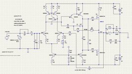
This is standard blameless topology with LTP, darlington VAS and (misconfigured ?) TMC, where it could go from there ? 🙂
Further improvement is possible (as mentioned by Bonsai), but these are just details. As a topology, it is what it is...
For example, instead of LTP we could use JFET op-amp, and make it push-pull: see this amp
https://www.diyaudio.com/community/threads/latfet-amp-based-on-philips-ah578.367494/
Last edited:
I didn't use mosfets but the STD03N and STD03P instead. They aren't in the Microcap lib so I used BD139-16 and D44VH10_ON and the complementary set. The "formula" is easy: 1 opamp drives the darlingtons (gain set at 9.2, noninverting) and the 2nd opamp drives the 1st (gain set at 10, inverting). Unfortunately the opamp LM49860 is unobtainium so one either has to use lower supply voltage for available opamp and use 2 circuits in a bridge for more power . IOW the "formula" is a case of nested feedback. Stability could be better but for a start I think it's OK.This looks incredibly good. How good are the lateral Mosfet models, aren’t they only simplified versions?
https://www.diyaudio.com/community/...f08n20v-alf08p20v-alf16n20w-alf16p20w.241619/
I see, in my sim I used 2 diodes instead (1.3V)...
I thought TLV431 was 1.24V
With 2 diodes however, the VAS current matches Lineup's 4.8mA, so something doesn't fit here....
Anyway, with 2 diodes instead of TLV431, LTP and VAS currents matches currents marked on the schematic in post #1.
I would go for slightly higher VAS current (say 8mA), but we will see, I'll experiment with this sim later on...
EDIT:
https://www.ti.com/lit/ds/symlink/tlv431.pdf?ts=1701847404766
TLV431 is 1.24V. It's different than TL431.
So 2 diodes should be fine.
Last edited:
Here is open loop gain/phase plots.
Phase margin: 80, and gain margin: 28.
Rock solid. Congrats Lineup! To me, so far only the TMC values look little suspicious, but other than that, the amp looks great.
That's with resistive-only load.
This should be repeated with some capacitance added to the speaker, but perhaps Lineup have already done that...
New sim attached, a new 'probe' net name has been added to sim the OLG.
Attachments
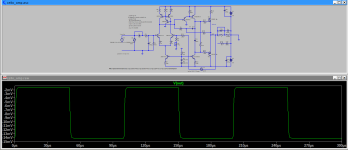
Here is close-up on 1kHz square wave (Vpp = 30V), seems like slew rate estimate is 12 V/us.
Perfectly adequate for a 20W amp. Rise time is not the same thing as SR, but it's just a guesstimate...

With Vpp=5V, there is some small overshot visible on the lower edge:

Perfectly adequate for a 20W amp. Rise time is not the same thing as SR, but it's just a guesstimate...
With Vpp=5V, there is some small overshot visible on the lower edge:
Attachments
With a 1uF capacitor in parralel with the load it oscillate.
One solution, and in fact the problem, is to increase the TMC 100R resistor up to 1k, but then distorsion will
increase accordingly, the low rate simulated is right but that s obtained at the expense of inconditionnal stability.
One solution, and in fact the problem, is to increase the TMC 100R resistor up to 1k, but then distorsion will
increase accordingly, the low rate simulated is right but that s obtained at the expense of inconditionnal stability.
I made the simulation with two parraleled pairs 2SJ50/2SK135 and 2SJ162/2SK1058, that should be more robust than a single Exicon pair as far as we re talking stability, gain should be increased by reducing the FB 1.8k resistance down to 1k for a 27 dB gain that suit better 5.1/7.1 systems wich require about 30dB gain for the amplifier.
The TMC network should be re calculated, not counting that 6mA is lot for the differential, such a high value is not necessary and necessitate big capacitors for the compensation.
Also a few resistances should be added to limit the current in some paths in case there s an abrupt non linearity that occur when the amp is hard clipped.
I tried to adjust the TMC circuit, here are initial results:
Thd at 1kHz: 0.000050% (full power)
Thd at 20kHz: 0.019115%
Slew rate (estimate): 42 V/us
Phase Margin: 74
Gain Margin: 15
I also increased VAS current to 8.5mA.
Lineup, I hope you don't mind me messing with your amp. Please review and let us know if these changes make sense?


FFT looks good, with floor at -210 dB, and all harmonics below audible level of -120dB

Thd at 1kHz: 0.000050% (full power)
Thd at 20kHz: 0.019115%
Slew rate (estimate): 42 V/us
Phase Margin: 74
Gain Margin: 15
I also increased VAS current to 8.5mA.
Lineup, I hope you don't mind me messing with your amp. Please review and let us know if these changes make sense?
FFT looks good, with floor at -210 dB, and all harmonics below audible level of -120dB
Attachments
Last edited:
H
HAYK
H
HAYK
You can replace the TLV431 with LM317L with adj. pin on -20v, ground on input, the out gives 1.24v
TLV431 is 1.24VFor the LTp current I am getting (2.5V-0.6V)/100 = 19mA. Am I reading the schema correctly? I am assuming the TL431 is 2.5V.
I think this is a nice, simple design. Let’s help Lineup make it better 😊
I may increase resistor at the TMC.With a 1uF capacitor in parralel with the load it oscillate.
One solution, and in fact the problem, is to increase the TMC 100R resistor up to 1k, but then distorsion will
increase accordingly, the low rate simulated is right but that s obtained at the expense of inconditionnal stability.
As you say it will increase distortion.
But it is important to get a stable amplifier.
I will test stability with 200nF across the load..
So many suggestions. And some say so and other say so.
I really have got people going 🙂
- Home
- Amplifiers
- Solid State
- Cello One. Good Amplifier 15 Watt with TMC and Laterals