Okay that's fine, is there anywhere i can get that transformer without having to wait like 2 or 3 months?
What about RS?
(As for VA rating and voltage I'm just going off what others have said are the correct requirements, 24 volt 160 VA).
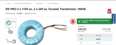
RS PRO 2 x 115V ac, 2 x 24V ac Toroidal Transformer, 160VA | RS Components
(As for VA rating and voltage I'm just going off what others have said are the correct requirements, 24 volt 160 VA).
RS PRO 2 x 115V ac, 2 x 24V ac Toroidal Transformer, 160VA | RS Components
Attachments
The one I offered is still available for immediate delivery.
24-0-24.
Plus phono stage thrown in for free.
And half the price INCLUDING delivery.
24-0-24.
Plus phono stage thrown in for free.
And half the price INCLUDING delivery.
I have the transformer which russc has sent. My question are:
Firstly, On the transformer in the amp it has 6 wires where the one i got has 5 so im not sure what to do.
Secondly, i need to remove hot glue to get transformer out but dont know how to remove without damaging components.
Firstly, On the transformer in the amp it has 6 wires where the one i got has 5 so im not sure what to do.
Secondly, i need to remove hot glue to get transformer out but dont know how to remove without damaging components.
Hot glue can usually be carefully pulled, picked and snipped off using cutters.
If you are totally unsure about the transformer then lets wait for russc.
Otherwise we need to see pictures and you need to first identify secondary from primary windings before going any further.
If you are totally unsure about the transformer then lets wait for russc.
Otherwise we need to see pictures and you need to first identify secondary from primary windings before going any further.
Hi.
Glad it arrived safely.
Brown & blue are mains in (match European standard live/neutral colours).
Ensure brown goes to live (fused) side.
Ref your photo, post #5. You will see white & red go to a common connection.
With the replacement transformer, this is a single red wire.
Original has 2 secondaries with separate wires, the replacement is the same but the secondaries are already connected at the transformer. AKA centre tap.
The other secondary wires are both orange.
Orange correspond to Yellow (AC1), the other orange to violet (AC2). It does not matter which way the orange are fitted (AC1 or AC2).
I hope all is clear?
I have installed the new transformer but have not soldered it yet.is there any precautions once ive soldered it that i should be doing so that i dont break this transformer?
So you dont break the amp - get a light bulb holder, and wire it in SERIES with the live wire. Fit an incandescent or halogen lamp (not a CCFL or LED) of about 60W or equivalent.
If everything is wired correctly, the bulb should light briefly and settle to a dim glow within a second or so when you turn the power on. If the bulb lights and stays lit, there is a fault.
If everything is wired correctly, the bulb should light briefly and settle to a dim glow within a second or so when you turn the power on. If the bulb lights and stays lit, there is a fault.
In case you aren't sure what to build or what you need for this current limiting device, often called a "Lightbulb Limiter" or "Dim bulb tester", there are plenty of references and pics on the net but the big issue is safety and you will need a means of protecting yourself and any others who like to touch things, from coming in contact with mains power, limited or not.
If you can afford one, use a mains rated, switched outlet box and mount it properly to keep the wiring safe but a table lamp can also be borrowed and used as a switched assembly and bulb holder, all in one. Any mains rated cable necessary to adapt the wiring for powering the device under test can be extracted from unused, heavy duty power leads.
The basic idea and schematic, though not being the safest way to isolate you from live mains, is easily seen here: Powering Your Radio Safely with a Dim-bulb Tester
Stand back, with unit switched on, plug in to mains.
Observe reading on meter. Expect around 30 to 50V AC for a working transformer. Zero for a dead transformer.
Report back.
So do it blow up or is it working ?
Last edited:
So replaced the amp and it turns on!!!!! 😀
Thank you guys, you have been an amazing and very good help.
Thank you guys, you have been an amazing and very good help.
Bias/Idle current
Ok here we are again and hope that everybody had a good holidays and new year.
Small question regarding this little amplifier and his idle current.
Amplifier is working fine but still can't get it to warn up as it should it stays stone cold even after 3 or 4 hours of music.
Original transistors were replaced by more powerful replacements after 1 channel failure (bought it faulty ) but measured 3mV idle current on the original working channel.
Replacements as follow
Originals - TIP3055/2955 - Vcbo 100V, Vceo 60V, Ic 15A, Ic 7A, Ptot 90W
Replacements - 2SD1047/2SB817 - Vcbo 200V, Vceo 140, Ic 12A, Icm 6V and Ptot 100W
Or did I make a mistake in using the 2sd10147/817 as a replacent ?
Regards
Last edited:
Possibly a slightly different turn on voltage of the different transistors that bring the adjustment out of range.
If you post the circuit showing the bias generator (and if this is the reason) then it should be easily tweakable.
If you post the circuit showing the bias generator (and if this is the reason) then it should be easily tweakable.
Hi and thanks Mooly
My 1st problem is I don't know exactly what P/N of the original transistors in my searches I have seen reports of Tip3055/2955 and TIP33/34 and other Japanese 2SD/2SB units.
Schematics are nowhere to be found.
I could take a picture of the board (top & bottom ) but that would involve taking the amp apart again.
- Home
- Amplifiers
- Solid State
- Cambridge audio a1 mk1 not powering on.