To OldDIY
That's correct and that's what I have done but...
Tip3055/2955 have a base turn on of 5V and the 2sd1047/2sb817 has one of 7V
I probably will try 2 sets of 2SB688/2SD718 and see how it goes
That's correct and that's what I have done but...
Tip3055/2955 have a base turn on of 5V and the 2sd1047/2sb817 has one of 7V
I probably will try 2 sets of 2SB688/2SD718 and see how it goes
All those transistors have a 'turn on' voltage of around 550 to 700 millivolts (all normal silicon transistors we use are in that ballpark) but seemingly very small differences can put bias adjustments out of range on some designs.
The turn on voltage is the voltage needed across the base and emitter junction for the device to begin to conduct. You can not drive the base higher than these values as it automatically the voltage between these levels.
If you measure 5 volt or 7 volt or 700 volt on the base then it means the emitter will be at that same voltage -/+ 0.55 to 0.7 volts. The - or + depends whether it is NPN or PNP as to whether the base or the emitter is the higher of the two.
Yes they are.
Are you confusing reverse B-E voltage which is in the 5 to 8 volt range for most transistors? That is not a turn on voltage, it is a voltage at which the junction breaks down and behaves more like a Zener diode. If the current is not limited the transistor is destroyed.
This is a condition that none of the transistors will encounter in a typical audio amplifier.
I checked so many datasheets that I may have gone confused..
Anyway the amplifier with the 2SD1047/2SB817 with the same exact idle current (3mV) works perfectly but the heatsinks stay cold as ice even after 3 or 4 hours of music with the volume at 11 o'clock.
I raised the idle current to 5mV and it's the same (cold heatsinks)
Can it be that the 3055/2955 heat up because they are closer to their limit ?
Last edited:
Without knowing the circuit I can't really say what you are actually measuring here but 3mv is a voltage not a current.... so I don't know quite what that is without seeing a circuit.
Bias current is often measured by taking a voltage reading across a low value resistor (such as an emitter resistor of the power output stage) and calculating the current from that.
If the same current is flowing in any type of transistor you might fit (and assuming the voltage across the transistor remains the same) then the power dissipated in the transistor will also be the same as well.
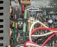
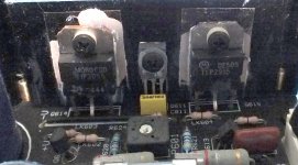
Does it look like this from earlier in the thread?
If so then the bias current is measured by taking a voltage reading across either of the two wire wound resistors.
There should be no signal and no load attached.
I can't make the value out from the picture but 0.22 ohm would be a common value.
A typical current might be around 100 milliamps and so that would be 22 millivolts across the resistor. Manufacturers sometime bias low to aid reliability and cool running due to commercial restraints on heatsink size and so on.
Attachments
Yes that is the one, measured across the 0.22 ohms resistor exactly 5.2mV on both channels
The other thing is that the trim pots are almost maxed out (470 Ohms)
I'm trying to upload a few pictures but they are over the sites limit.
The other thing is that the trim pots are almost maxed out (470 Ohms)
I'm trying to upload a few pictures but they are over the sites limit.
Last edited:
5 millivolts is only 22 milliamps and if the voltage across the transistor is say 30 volts (it will be the rail voltage whatever that is) then the dissipation is only 0.66 watt. Hardly anything in other words.
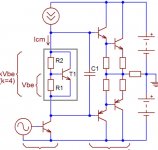
The middle transistor on the heatsink is the 'vbe multiplier' and probably looks a bit like this.
You will need to study how yours is configured but I would guess that R1 (most likely) or R2 is the preset. You need to see if there are any series resistors going to the preset end pins and work out which one to increase or decrease the value of to get more range on the control.
I would suggest you use a bulb tester initially if you alter anything because if you get it wrong the current could be very high and cause damage.
Attachments
There is definitely something wrong and I think is output transistors related because I can't find a single faulty component.
Can someone confirm this (output transistors P/N) BananaDriller ??
Can someone confirm this (output transistors P/N) BananaDriller ??
Last edited:
You will not find a faulty component if the problem is caused by the adjustment being out of range due to differing characteristics Vbe of the replacement devices.
Its a two minute fix if this is the problem.
Its a two minute fix if this is the problem.
2 minute job if you know how to do it and I'm no good at altering circuits/components I can fix then with the correct (read original) components.
Lets try this if you are willing to help me.
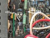
R620 goes from Vbe multiplier to "wiper" leg and R621 again from Vbe to lower let on trim pot going to open the amp to check values and vbe transistor p/n.
R620 = 1K5, R621 =470 Ohms and Vbe transistor = BD139
Please check picture on page 10 post 94
Lets try this if you are willing to help me.
R620 goes from Vbe multiplier to "wiper" leg and R621 again from Vbe to lower let on trim pot going to open the amp to check values and vbe transistor p/n.
R620 = 1K5, R621 =470 Ohms and Vbe transistor = BD139
Please check picture on page 10 post 94
Last edited:
Its difficult without seeing it tbh 🙂
Does this pin connect to the base of the multiplier?
Pictures:
How to attach images to your posts.
Does this pin connect to the base of the multiplier?
Pictures:
How to attach images to your posts.
Attachments
My A1. TIP2955/3055. Pics might help with component values.
You can have the board for price of postage plus a pint of ale.
Been in loft for years, working when put there but wouldn't vouch for it now.
No transformer or phono board.
You can have the board for price of postage plus a pint of ale.
Been in loft for years, working when put there but wouldn't vouch for it now.
No transformer or phono board.
Attachments
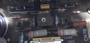
Going a bit Neanderthal but I scribbled the components on the pic on post 94 have a look
Mooly my problem is they are to big (over 5mb each)
Rusc thanks for the offer but like I mentioned before mine is working just not warming up due to different output transistors but if i don't get to the bottom of it I'll come back to your offer.
Mooly my problem is they are to big (over 5mb each)
Rusc thanks for the offer but like I mentioned before mine is working just not warming up due to different output transistors but if i don't get to the bottom of it I'll come back to your offer.
Attachments
Last edited:
Just one more thing the BD139 is reversed (plastic face against the heatsink)
 that explains a lot... I was struggling to figure the configuration out.
Lets try again then...
So it looks like the preset and its series 470 ohm is between base and emitter.
There is then a 1k between base and collector.
To get more range on the preset you need to decrease the 470 ohm fixed resistor. It is important that you first turn the preset to give MINIMUM bias by setting it to its maximum value. That means the preset should read as 470 ohm when set to maximum and not zero ohm.
I would try a 390 ohm for that fixed resistor and I also have to add the mantra of using a bulb.
You could also (if easier) just tag a 2k2 across the 470 ohm fixed resistor to bring its value down.
I'll have to leave it for now but I'll look in later 🙂
- Home
- Amplifiers
- Solid State
- Cambridge audio a1 mk1 not powering on.