What brand of caps do you use on C2, i was thinking of buying Nichicon UFW Standard 50V 6800uF.
Is this CAP any good?
Is this CAP any good?
Last edited:
If you are using the store MoFo PCBs, then you are limited to a lead spacing of 7.5mm and a lead diameter of 0.8mm, though 0.7mm is easier to fit. Maximum case diameter would be 20 or 22mm, depending on what connectors you are using on the output. The Nichicon UFW 6800 uF, 50V part is too big to fit on the PCB. Good news is that the Nichicon UKW 6800 uF, 25V part is a perfect fit, and a better quality cap.
Thank you, I am going to do Point-to-point construction and i think is going to have lots of space, because of the heatsinks 🙂 I think the coils going to be Microwave TRs.
I got two MOTs from different sources to try out. Their markings are identical. They are very closely matched for DC resistance: one is 0.498 Ohms and the other is 0.506 Ohms.
The main part number is MD-803AMR-1
The main part number is MD-803AMR-1
Last edited:
Rather late to the party but I have rather a lot of time on my hands 😉
I'm running the B1 Korg as preamp but will need a little lift for the MoFo. Reading back to post 1172.
Could I just pop 2x Edcor 600/15k in the case on the inputs of MoFo?
Well, i did some measurements today and i am a bit confused.
When the Korg delivers 1V into the Edcor, the Edcor delivers at about 6V and the distortion spectrum is faithfully reproduced
But at low voltages this is no longer the case. Below 1.6 V measured at the Edcor the third harmonic is dominant. I have no explanation for that. I would expect that the buffer of the Korg keeps things under control regardless of the output voltage??
Anybody has an explanation
pdf of measurements attached
Attachments
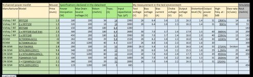
After several tests with different mosfets I came to these conclusions.
A single mosfet cannot dissipate effectively on a very large heatsink and therefore above 60-70W two mosfets must be used.
Parallel mosfets that work with different bias currents create high frequency distortions and therefore you have to make a selection or use independent bias.
An independent bias mean 2 trimmer and 2 interstage capacitors with high cost and also the noise can increase because you will use for each 220Kohm instead of 110Kohm to keep the same load for the driver stage.
As you can see from the table I have not found mosfets better than the IRFP150 and IRFP240 because if the frequency band and slew rate increases there is worsens output resistance that I would like to keep below 200mohm.
So I suggest IRFP150 or IRFP240 to dissipate up to 60W and 2 x IRFP240 selected to dissipate up to 120W.
Attachments
Last edited:
While trying to track down the source of excessive harmonic distortion while playing a 1.0 kHz sine wave, I have made a few changes on my MoFo PCB. First I added an extra power decoupling cap at the power entry point. After trying a few different types, the most effective one is a 440 uF, 50V aluminum organic polymer made by Kemet.
A759MX447M1HAAE028 KEMET | Mouser
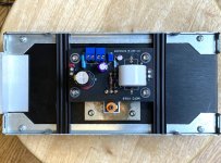
I have also added a 47 uF, 35V organic polymer cap across the bias trimmer, after the 15k resistor. These seem to help keep the local power on the PCB cleaner. While I initially chose the large Hammond 195T5 choke, it seems to be larger and heavier than I need, as I'm only running from 2.4 to 2.6 Amps bias current. Switching to a Microwave Oven Transformer seems to be working well so far. It has a lower DC resistance of 0.5 Ohms, and with higher quiescent bias current, maintains a more stable voltage across its terminals when playing the 1 kHz test signal.
I'm still working with a couple different SMPS units, trying to find the best combination of simple bypass vs. cap multiplier and final voltage at the MoFo board. With the newer configuration, 26V and 2.6A seems to give the lowest distortion, at the cost of extra heat.
I have addressed the higher power dissipation through a single IRFP250 with a copper heat spreader and ceramic insulator. The next step is to try some extra aluminum heat sinking around the PCB. I think both the IRFP250 and FQP44N10 should be able to handle the power, as long as I don't leave the monoblocks on 24/7 for weeks at a time. The next Mosfet to try will be the IXTH64N10L2, which is rated for even higher power dissipation.
A759MX447M1HAAE028 KEMET | Mouser
I have also added a 47 uF, 35V organic polymer cap across the bias trimmer, after the 15k resistor. These seem to help keep the local power on the PCB cleaner. While I initially chose the large Hammond 195T5 choke, it seems to be larger and heavier than I need, as I'm only running from 2.4 to 2.6 Amps bias current. Switching to a Microwave Oven Transformer seems to be working well so far. It has a lower DC resistance of 0.5 Ohms, and with higher quiescent bias current, maintains a more stable voltage across its terminals when playing the 1 kHz test signal.
I'm still working with a couple different SMPS units, trying to find the best combination of simple bypass vs. cap multiplier and final voltage at the MoFo board. With the newer configuration, 26V and 2.6A seems to give the lowest distortion, at the cost of extra heat.
I have addressed the higher power dissipation through a single IRFP250 with a copper heat spreader and ceramic insulator. The next step is to try some extra aluminum heat sinking around the PCB. I think both the IRFP250 and FQP44N10 should be able to handle the power, as long as I don't leave the monoblocks on 24/7 for weeks at a time. The next Mosfet to try will be the IXTH64N10L2, which is rated for even higher power dissipation.
Attachments
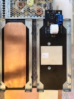
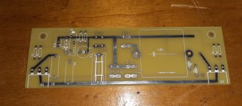
Here is my current MoFo channel board configuration. The extra aluminum pieces have been attached with thermal conductive epoxy. The heatsink is from a Mini Dissipante 3U, 250mm.
Notice the discoloration on the copper heat spreader. That's why I initially tin plated these pieces. I sanded this one slightly to make sure the surface was flat, and the heat caused the exposed copper to turn darker.
Notice the discoloration on the copper heat spreader. That's why I initially tin plated these pieces. I sanded this one slightly to make sure the surface was flat, and the heat caused the exposed copper to turn darker.
Attachments
I finally figured out the issue I have been having. My distortion analyzer works fine, but hooking up an oscilloscope to the speaker terminals causes a problem when the ground lead of the scope probe is attached to the negative speaker terminal. Very strange, what is technically known as bad Juju between the two components. I haven't seen this with any of the other amp builds I've done, so I'm guessing the choke loaded output may be a factor.
Anyway, now that I’ve solved the problem, the distortion measurement on the analyzer looks quite good. No issue it seems with the SMPS, so I've re-installed the first set of 150W, 27V supplies, and will proceed with those. Power supply filtering now consists of a simple CLC filter between the SMPS and the amp PCB. I've adjusted the power to be 26V at the PCB, with 2.4A quiescent current. The CLC is 8 uF film - 1 mH inductor - 27000 uF electrolytic, and does a nice job of reducing the supply noise delivered to the board. I've going to leave the MOTs in place and save the big honkin' 195T5 chokes for another project (Singing Bush). Time to finish building the second monoblock, and then hear what they sound like.
Anyway, now that I’ve solved the problem, the distortion measurement on the analyzer looks quite good. No issue it seems with the SMPS, so I've re-installed the first set of 150W, 27V supplies, and will proceed with those. Power supply filtering now consists of a simple CLC filter between the SMPS and the amp PCB. I've adjusted the power to be 26V at the PCB, with 2.4A quiescent current. The CLC is 8 uF film - 1 mH inductor - 27000 uF electrolytic, and does a nice job of reducing the supply noise delivered to the board. I've going to leave the MOTs in place and save the big honkin' 195T5 chokes for another project (Singing Bush). Time to finish building the second monoblock, and then hear what they sound like.
Last edited:
I have tested 3 different types of insulators for the assembly of mosfets.
Environment 2 x IRFP240 total 30.9VDC 3.66A 113W to dissipate on Hi-Fi2000 heatsink 3 units H120 (smaller than what will used).
The sensor was in the center of heatsink.
Sil-Pad Bergquist SP400-0.007-00-104 (RS 707-3367)
time (min) degrees (°C)
0 27
5 42
10 52
15 58
20 62
Thermally Conductive Insulator Aavid 4180G +
Thermal Interface Products Accessory / Grease Aavid 101800F00000G
0 27
5 42
10 53
15 57
20 60
kapton film +
Thermal Interface Products Accessory / Grease Aavid 101800F00000G
0 27
5 42
10 52
15 57
20 60
So the Sil-Pad it has been confirmed as valid and easier to use.
Last edited:
measure temp at mosfet drain pin
heatsink will eventually get its temperature even through block of concrete, if mosfet remain alive
heatsink will eventually get its temperature even through block of concrete, if mosfet remain alive
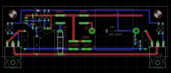
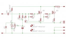
Pcb ready, I will test soon
I will test in this configuration FQH44N10-F133 and IRFP240 with a selection for the bias point.
I will test in this configuration FQH44N10-F133 and IRFP240 with a selection for the bias point.
Attachments
Last edited:

it smells as new battery for DMM
Another Gotcha that can waste your day are the open circuit aligator clip leads from China. They don't make them like we used to.
I've got my MoFo up and running (blows away my gainclone!), but I have a problem w/ one channel that I can't figure out.
If the input resistance to ground is less than ~45R, the bias voltage goes up by ~2.5x (the other channel's drops ~5%). This happens, for example, when I turn the volume all the way down on my passive pre. My Amp Camp Pre has 33R to ground across the output, so I can't use it until I fix this.
I'm running both channels off one brick in parallel, and both see the same 20V. I have the suggested Zeners installed. I can't see any bad solder joints or bridges, and various resistances measure the same on both boards. When I put my ear next to the tweeter on the bad channel, I can hear a quiet screechy noise - the other is silent.
Any idea what could be going on here?
The input coupling cap, is it electrolytic? check the orientation - the negative leg connects to the input.
Last edited:
Polypro, per the BOM. And I checked the relative orientation of the output caps, which are electrolytic, and they're the same. I tried the capacitance feature on my DMM, but couldn't get a reading. Either I don't know how to use it, it doesn't work, or the rest of the circuit is preventing a reading.
Thanks for the suggestion.
Thanks for the suggestion.
Pcb ready, I will test soon
I will test in this configuration FQH44N10-F133 and IRFP240 with a selection for the bias point.
if i were doing that, i will provide individual gate bias pot for mosfets, my reasoning is that no two mosfets bias alike....
My MoFo's are back into parts as it took up too much space as my "active" amps now are my M2X's and I will keep them for a while.
If anyone close to Copenhagen what to build a MoFo using 20 kg chokes (50 mH, 73 mOhm) made with 12,5 mm2 cupper wire we may find out of something. I was very pleased with the result. I operated the MoFo at 26 VDC at 3A bias. The chokes can handle much more DC current (the limitation is the heatsinking of the mosfet). The low DC resistance in the chokes did not cause any problems with unstable bias etc.
If anyone close to Copenhagen what to build a MoFo using 20 kg chokes (50 mH, 73 mOhm) made with 12,5 mm2 cupper wire we may find out of something. I was very pleased with the result. I operated the MoFo at 26 VDC at 3A bias. The chokes can handle much more DC current (the limitation is the heatsinking of the mosfet). The low DC resistance in the chokes did not cause any problems with unstable bias etc.
Attachments
- Home
- Amplifiers
- Pass Labs
- Build This MoFo!